background image

SK00-4390-DI-002-11


12 


The machine is designed not to cause any leakage under restricted


condition and demonstrated by the Leak test. However, it still has a 

risk of leaking under any abnormal condition other than specified, for 

example abnormal water pressure rise. In such a case, the leakage 

shall remain unstopped unless the supply from the system stops. You 

should refrain from installing electrical equipment or wiring beneath 

the Pump and on the floor around the Pump. 


We recommend you to put the Leak sensor on the floor beneath the 

Pump and engage it with the interlock system of the equipment. Close 

the Coolant supply valve (HWSV) immediately you noticed the leakage. 

Put the [Closed] tag onto the handle after having closed the valve. 


Put a Flow meter (HWFM: for example Flow sight) applicable to


visuallycheck the flow onto the Coolant supply source to make it 

possibleto check the flow.


If you use several pumps, be sure to connect the Coolant pipes 

parallel. 

Cooling capacity might come down if connected them serial and cause 

thefailure. 


You should put a filter at the front stage if you are obliged to use the 

water containing much impurity such like water stain, iron and the like. 


Appropriate flow might not be ensured when the supply source and 

discharge outlet were apart or there was level difference in the 

piping(discharge outlet was elevated higher than the Pump). In such a 

case,cause a measure to ensure the flow volume, such as to change 

the piping layout, put a larger pipe or raise the supply pressure within 

thespecification range.


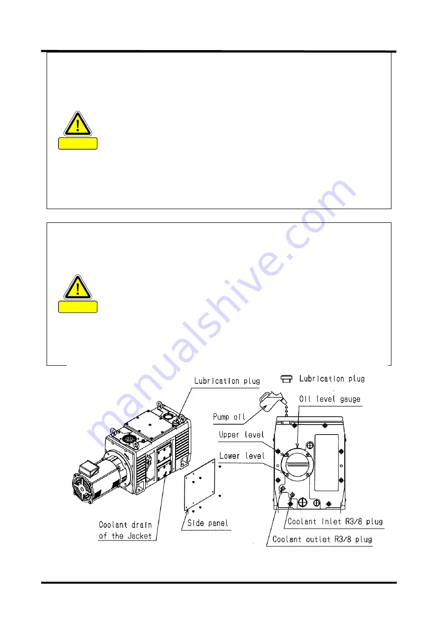
Fig. 4 Lubrication and water piping drawing 

CAUTION


Summary of Contents for VS1501

Page 1: ...STRUCTION MANUAL OIL SEALED ROTARY VACUUM PUMP VS1501 VS2401 Before using this product be sure to read this operation manual Keep this manual with care to use at any time ULVAC Inc Components Division...

Page 2: ......

Page 3: ...ensured if any of the devices put together did not conform to same regulations or the product itself was modified ULVAC shall be not liable to guarantee performance and safety in such cases above Any...

Page 4: ...d below 0 2 Meanings of Safety Symbol Marks DANGER If the user makes a mistake in handling it indicates an imminent possibility that the user is subject to death or heavy injury If the user makes a mi...

Page 5: ...inactive gas is not allowed as there is a risk of leakage of the gas from the Pump unit if it was exhausted by the vacuum pump DANGER Pump oil as well as the Pump unit becomes toxic should the toxic g...

Page 6: ...al please feel free to contact our Components Division This Instruction Manual shall absolutely need to be delivered to the last user that uses the product To export this product abroad you have to cl...

Page 7: ...ent You are strictly restricted to enter beneath the Pump Advise the dismantling agent to wear leather gloves and use appropriate tools such as pinch bar as they have a risk of cutting the hand by nai...

Page 8: ...cal shock in case of failure or electric leakage It is imperative to put the Overload protection device Otherwise it would cause the motor burn out and or fire Wire size please determined by consideri...

Page 9: ...Service Center for check and repair Do not attempt to put your hand or article in the opening of the motor you have a risk of getting electrical shock injury or casing a fire Do not touch any rotary s...

Page 10: ...wall of cooling water tube is covered with water scale CaCO3 etc and cooling water flow rate may be decreased Cooling water tube is corroded by Chlorine ion Cl and cooling water leak may be caused In...

Page 11: ...ature cools down Use a flow meter HWFM for example Flow sight applicable to visually check the Coolant supply source that no water is flowing Inlet piping Dismantling Take off the piping following the...

Page 12: ...ture Ensured pressure value of the Pump shall be 0 03MPaG 0 3kg cm2G Gauge pressure Do not run the Pump on blocking the Exhaust outlet or putting any device that might hamper gas passage onto the outl...

Page 13: ...SK00 4390 DI 002 11 xi Fig 1 Warning Label display position...

Page 14: ...asonable operation or machinery setup was not sufficient You are strictly restricted to enter beneath the Pump Advise the dismantling agent to wear leather gloves and use appropriate tools such as pin...

Page 15: ...provided with this machine be sure to fulfill the following for its storage install and operation 1 Ambient temperature and humidity for storage 30 C to 60 C less than 95 RH 2 Ambient temperature and...

Page 16: ...o 3 1 Storage Installation too Model Foot print Bolt Anti vibration Rubber mount VS1501 VS2401 The Pump has four holes The Pump is fixed with four bolts More than M12 x 40mm Kurashiki Kako Ltd Model K...

Page 17: ...SK00 4390 DI 002 11 xv It is imperative to put the Overload protection device Otherwise it would cause the motor burn out and or fire WARNING...

Page 18: ...t Intrinsic Hazardous Nature and Safety Measures 1 1 1 1 Danger Leakage of dangerous gas and dangerous materials 1 1 1 2 Warning Transfer of heavy material 1 1 1 3 Warning Electric shock 2 1 1 4 Warni...

Page 19: ...Checking The Coupling and Spider 34 6 2 9 Checking The Oil Mist Trap 35 6 2 10 Adjusting The Slow Leak Valve 36 6 2 11 Replacing The Exhaust Valve Vane 36 6 2 12 Cleaning The Coolant Jacket 40 6 2 13...

Page 20: ...on pressure and pumping speed MODEL VS1501 29 Fig 9 Show the relationship between the suction pressure and pumping speed MODEL VS2401 29 Fig 10 Replacement of coupling spider 35 Fig 11 Slow leak valve...

Page 21: ...t exhaust any hazardous gas such as toxic and combustible When you check the Pump please wear a brace that supports the toxic substances that exhaust the Pump To overhaul or dispose ask the special ag...

Page 22: ...n the hand or bar into the opening of the Motor Motor terminal mount gets burnt Tighten close the terminal Check the tightening once a month Refer to 3 6 Electrical connection 1 1 4 Warning Explosion...

Page 23: ...until the temperature sufficiently cools down after having stopped the pump to conduct check or something Do not touch the Pump unit or the Motor when operating the Gas ballast port 1 1 6 Caution Lea...

Page 24: ...need Read it with attention to acknowledge the toxic characteristics described on the SDS Please contact us separately if you want to use any chemical material Vacuum pump oil other than described on...

Page 25: ...pressure 4 Adopted hydraulic oil anti suck method If you stopped the Pump long time by a sudden blackout without returning the Suction line to the atmospheric pressure the pump oil might flow back in...

Page 26: ...MPaG Gauge pressure 0 1 Temperature C 5 30 Weight kg 232 271 1 The ultimate pressure is the value indicated on the Pirani gauge when the standard oil ULVOIL R 72 is used The ultimate pressure when the...

Page 27: ...SK00 4390 DI 002 11 7 Fig 2 VS1501 Dimensional drawing...

Page 28: ...SK00 4390 DI 002 11 8 Fig 3 VS2401 Dimensional drawing...

Page 29: ...ing and have special knowledge skill and title regarding the electricity machinery cargo vacuum and so on Be sure to clear any energy sources e g electricity coolant and so on of the product before in...

Page 30: ...et previously before starting lubrication Please obtain the latest version of Safety Data Sheet SDS from our Sales Department Weal protective gears such as rubber gloves protective goggle and so on Sh...

Page 31: ...inter the water piping and Jacket have a risk of breaking by freeze up of the water inside Open the Coolant drain of the Jacket Refer to Fig 4 during operation stop to discharge the water inside by bl...

Page 32: ...he handle after having closed the valve Put a Flow meter HWFM for example Flow sight applicable to visuallycheck the flow onto the Coolant supply source to make it possibleto check the flow If you use...

Page 33: ...oreign substance enter inside Should the Pump sucked the water or substance such as dust powder and so on it would impair the ultimate pressure and further cause a trouble The Pump has a really slight...

Page 34: ...pressure 10kPa atmospheric pressure continuous operation Further it is also required to collect the oil pooled in the trap to decrease the oil consumption Refer to Fig 2 and 3 Oil mist trap return por...

Page 35: ...to exhaust any combustible combustion susceptible or corrosive gas be sure to use pipes made of high pressure withstanding and corrosion resistant metal Ensure also to take a grounding In the case of...

Page 36: ...SK00 4390 DI 002 11 16 Fig 5 Suction Exhaust piping connection diagram...

Page 37: ...h with 200V and 400V class utilities by changing wire connection in the motor terminal box because multi voltage motor for both 200V and 400V classes is used for this pump WARNING Before wiring please...

Page 38: ...dering the voltage drop of the wire Typically the voltage drop please to be within 2 of the rated voltage of the motor Voltage drop calculation 3 wire resistance km Wiring length m motor rated current...

Page 39: ...to ground the motor ground terminal 200V 240V Ground to 100ohm or less 380V 460V Ground to 10 ohm or less Use a safety circuit which keeps the motor from starting a fire which is caused by over curre...

Page 40: ...ENT A RATED VOLTAGE V 12 the connection inside the terminal box 7 5 4 VS2401 3 Totally Enclosed Fan Cooled Flange Induction Motor VS1501 5 5 4 Table 4 Terminal box main dimension TYPE VS1501 VS2401 Ea...

Page 41: ...ressure structure Ensured pressure value of the Pump shall be 0 03MPaG 0 3kg cm2 G Gauge pressure If any valve was put to a pipe after the Exhaust outlet check and ensure that it is open WARNING Never...

Page 42: ...as acid immediately replace the oil as it would cause the rust during the stop in one night to make the system e not applicable to operate We shall be not liable to the durability to chemical material...

Page 43: ...e The pressure shall come down if the rotation direction was correct clockwise viewed from the Motor If it rotated reverse the Power Supply phase is reversed Replace connection of two of three wires s...

Page 44: ...he process described below if the rotation at start was not smooth Check first the oil level and fill it appropriately The oil might enter inside the Pump cylinder if you left the Pump stopped longtim...

Page 45: ...mp if failed in following this procedure the Pump cylinder gets filled with the oil in several minutes which might make difficult to restart operation or give damage to the Pump unit Further the oil m...

Page 46: ...s performance Note further that keeping the Gas ballast valve open when not breathing in the condensed gas shall cause the Pump oil splashing and power loss and further rise the ultimate pressure You...

Page 47: ...apacity of the motor overload protective device conforms to the motor rated value and warm up the Pump oil or replace the oil with the Vacuum pump oil ULVOIL R 42 having lower viscosity CAUTION Pump r...

Page 48: ...the site shall likely to raise the ultimate value higher than the catalogue value as the vacuum gauge was put far away from the Pump or maybe affected by the water drop rust or other substances attach...

Page 49: ...allast opened Pumping Speed Type VS1501 Power 50 60Hz AC200V 5 5kW Oil ULVOIL R 72 Gauge Porani Oil Manometer Hg Manometer Pumping speed 60Hz Pumping speed 50Hz Motor current 50Hz Motor current 60Hz 8...

Page 50: ...pression work is large even the suction pressure was small Further when the temperature of the Pump site was low in cold district or outdoor installation starting the Pump would require larger motive...

Page 51: ...hough you have to consider checkpoints depending on the use of the Pump you should check the following regularly it is helpful to avoid trouble and extend the pump life cycle WARNING Check and ensure...

Page 52: ...must be changed several times If the pump is operated using pump oil containing much moisture content the ultimate pressure will rise leading to poor functioning of the mechanical friction parts of th...

Page 53: ...cified ultimate pressure cannot be attained by oil change sludge or other deposit may have collected on the bottom of the pump case In that event overhaul is required Contact your local ULVAC organiza...

Page 54: ...Vibration Checking around the pump 1 Check whether bolts and nuts and the like fixing the pump are loose or not 2 Check whether pipes connected to the inlet outlet are loose or not 3 Check and ensure...

Page 55: ...ould be in charge of operating the machine such as crane Fig 10 Replacement of coupling spider 6 2 9 Checking The Oil Mist Trap To use the Oil mist trap be cautious not to have clog of the filter in t...

Page 56: ...stops and keep it open around one minute Then rotate the slow leak valve clockwise until it stops and wait until the punch noise occurs Upon the punch noise occurred rotate the slow leak valve little...

Page 57: ...Required tools and parts Name Specifications Quantity VS1501 VS2401 VS1501 VS2401 Exhaust valve vane Exhaust valve vane A 2 1 Exhaust valve vane B 2 Exhaust valve gasket For VS1501 For VS2401 1 1 Req...

Page 58: ...cap screw M4 8 Exhaust valve vane A Exhaust valve vane B Exhaust valve guide Hexagon socket head cap screw M4 8 Exhaust valve seat Hexagon socket head cap screw M6 14 Top cover Hexagon socket head ca...

Page 59: ...sition of the exhaust valve to the following After having fixed it confirm that there are no deviation of the mounting position for the exhaust valve and no interval between the exhaust valve and the...

Page 60: ...found remarkable Pump contamination or performance deterioration due to the operation condition you are recommended to conduct the overhaul earlier than one year period You shall be in need of replaci...

Page 61: ...so as not to drop bolt or the like inside the Cylinder 2 Required tools and parts Name Specifications VS1501 VS2401 Hexagon wrench M10 Torque wrench M10 25 30Nm 3 Cleaning the Oil tank Operation 1 Re...

Page 62: ...ust valve unit and disassemble it to the exhaust valve seat the valve plate the valve guide Work Wipe off foreign objects sludge attached to each parts with solvents and soft waste Do not damage the s...

Page 63: ...e Center close to you listed at the end of the document as for the overhaul Do not remember to fill and submit the Contamination certificate enclosed in the end of the document WARNING We would be obl...

Page 64: ...e the Safety circuit conform to the Motor specification 3 Replace the oil 4 Conduct the overhaul replacement of the Cylinder Rotor Cover and so on 5 Conduct the overhaul cleaning inside the Pump remov...

Page 65: ...e not moving 7 Panel screw is loose 8 Oil is not filled Oil is under the lower limit of the Oil level gauge 4 Overhaul a Clean the oil pit b Check and repair the Oil distributor valve 5 a Keep flowing...

Page 66: ...he pipe connecting with the Pump 9 Not using the ULVAC genuine oil 1 Select another Pump type 2 Measure correctly the pressure 3 Use the Vacuum gauge that matches the measurement pressure range and co...

Page 67: ...e the Exhaust valve vane 3 2 6 2 11 Pump surface temperature is abnormally high Room temperature 60 C or more 1 Coolant does not flow Specified volume is not flowing 2 Keeping continuous operation und...

Page 68: ...is broken 4 Oil mist trap is clogged 1 Drain the oil until it gets the specified volume 2 Put the Oil mist trap on the Exhaust side 3 Replace the Exhaust valve vane 4 Replace the Filter element 3 2 6...

Page 69: ...lue 1 Foreign substance entered inside the Pump impaired the Motor rotation 2 Abnormal sliding of the Rotor and or vane 3 Keeping continuous operation under high suction pressure 1 Overhaul removal of...

Page 70: ...t allowed by the vacuum pump Pump oil as well as the Pump unit becomes toxic should the toxic gas was sucked in the vacuum pump Pay attention to execute maintenance work You should replace with the ni...

Page 71: ...larly if the Pump has exhausted any toxic gas Note that you are requested to bear the cost and charges relating to the disposal CAUTION You should ask a special disposal agency for the disposal partic...

Page 72: ...ications although this product is used under the service conditions described in this document such as temperature range and power etc 2 Direct export transaction Product which has damage caused by a...

Page 73: ...dary damage to Buyer by the reason that third party sued ULVAC for patent infringement 9 ULVAC engineer decided the reason of failure was improper use which does not conform to the use condition of th...

Page 74: ...os sheet 1 O ring P10A 1 Fluorine rubber 1 Oil distributor gasket Fluorine rubber 1 O ring P14 1 Fluorine rubber 1 O ring P18 1 Fluorine rubber 3 O ring P28 1 Fluorine rubber 1 O ring P36 1 Fluorine r...

Page 75: ...ty period Table Making format for names and contents of hazardous substances or elements Name of parts Hazardous substances or elements Pb Hg Cd Cr6 PBB PBDE Body indicating that content of the hazard...

Page 76: ...ion Remarks Contaminant Check an applicable box I guarantee that above returned item s is not contaminated with harmful substances Above returned item s is contaminated with the following harmful subs...

Page 77: ...o jp en Service Centers http www ulvac co jp en support service center Sales O ces http www ulvac co jp en support sales o ces 253 8543 TEL 0467 89 2261 108 0075 TEL 03 5769 5511 532 0003 TEL 06 6397...

Reviews: