SK00-4390-DI-002-11
36
6.2.10 Adjusting The Slow Leak Valve
This machine adopts the air introduction method to reduce the noise on achieving the
ultimate
pressure. If the Slow leak valve was clogged, a high sputtering sound (called “punch noise.”)
is
generated during operation on the ultimate pressure. Adjust the Slow leak valve in such a
case.
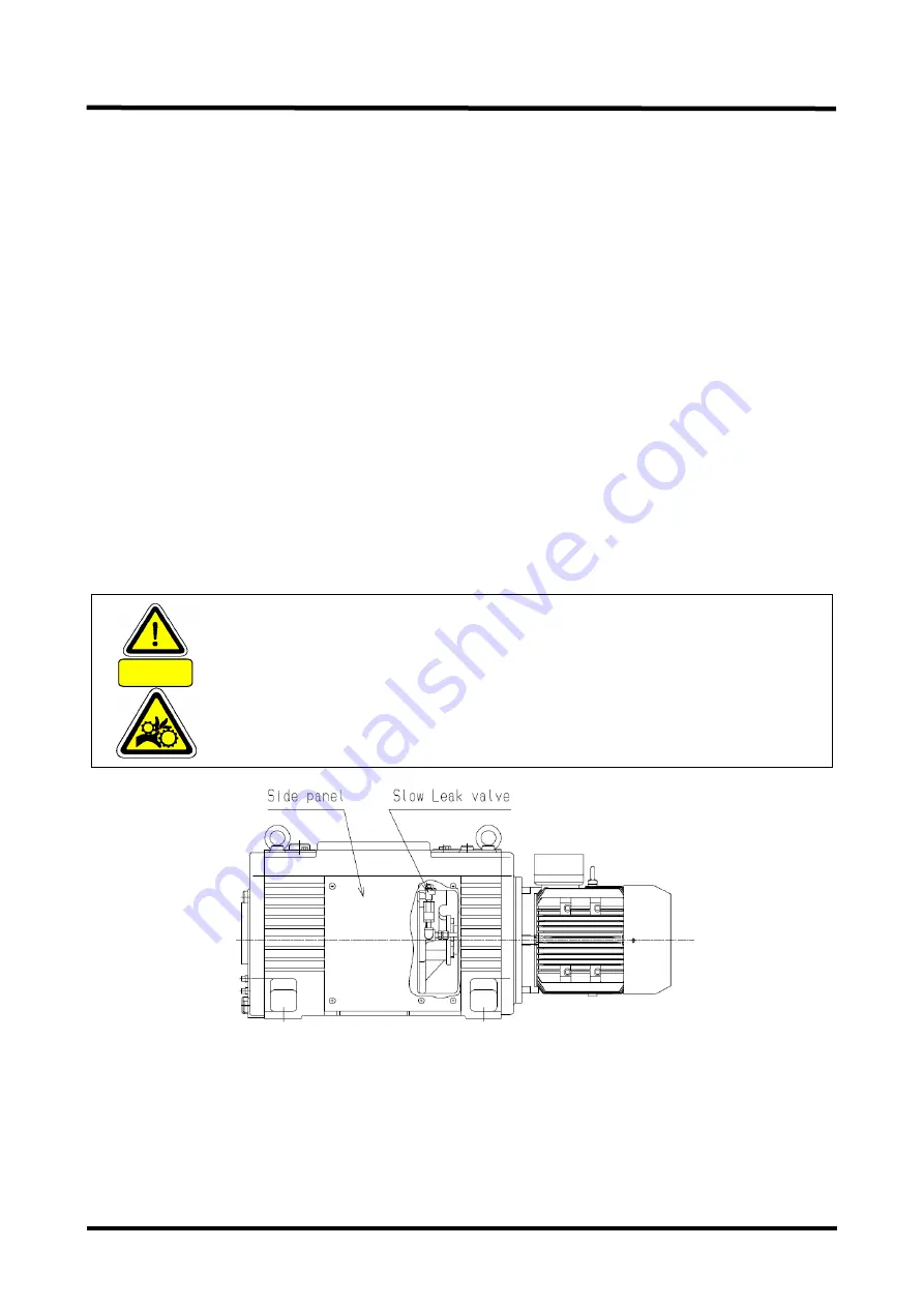
Shown below is the procedure to adjust the slow leak valve. (Refer to the “Fig. 11 Slow leak valve
adjustment”.) Put a pair of cotton gloves as the Pump system has high temperature sections.
(1) Take off the Side panel (at right viewed from the Level gauge) under the state operated
the
Pump on the ultimate pressure.
(2) Rotate the Slow leak valve at the Coupling section counterclockwise until it stops and
keep it open around one minute.
Then rotate the slow leak valve clockwise until it stops and wait until the punch noise occurs.
Upon the punch noise occurred, rotate the slow leak valve little by little counterclockwise until the
punch noise stops. Under this state, Tighten Lock nuts of the Slow leak valve.
CAUTION
Couplings are put close to the slow leak valve. Pay attention not to get
your hand caught during adjustment work or the like.
You are recommended to check the ultimate pressure when adjusted the
slow leak valve.
Pay attention not to open the slow leak valve too much as the ultimate
pressure would not come down to the specified pressure.
Fig. 11 Slow leak valve adjustment
6.2.11 Replacing The Exhaust Valve Vane
Replace the Exhaust valve vane every 9,000 hours. It might break earlier if the Pump sucked
the foreign substance or water.
Procedure to replace the Exhaust valve vane is shown on the next page.
Summary of Contents for VS1501
Page 2: ......
Page 13: ...SK00 4390 DI 002 11 xi Fig 1 Warning Label display position...
Page 27: ...SK00 4390 DI 002 11 7 Fig 2 VS1501 Dimensional drawing...
Page 28: ...SK00 4390 DI 002 11 8 Fig 3 VS2401 Dimensional drawing...
Page 36: ...SK00 4390 DI 002 11 16 Fig 5 Suction Exhaust piping connection diagram...


