INTRODUCTION
USER MANUAL — 74-36103-ENG R6
13
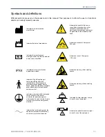
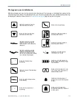
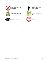
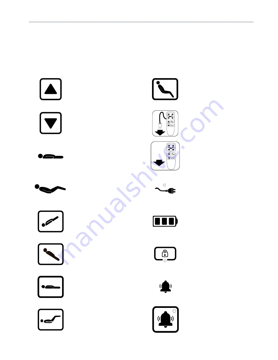
Pictograms and definitions
Different pictograms are used on the product and in this manual. Their purpose is to facilitate the reading and the
understanding of the different functionalities to the user. If bed is equipped with screen, additional pictograms may
be displayed in different menus. Refer to
Footboard control panel
(page 34) section if required.
Button for elevation of section
illustrated below the button
Button for lowering of section
illustrated over the button
Button for reverse Trendelenburg
positioning
Button for Trendelenburg
positioning
Illustration indicating possible
activation of Backrest section
AND/OR the Thigh Section per
use of one or both buttons located
over or below the pictogram
Illustration indicating possible
activation of Hi-Lo per use of
button located over or below the
pictogram
Button for the vascular foot
positioning
Button for patient sleep surface
flat positioning
Button for chair positioning
Illustration indicating location to
connect patient control
Button with LED indicator for
activation/deactivation, of bed exit
control system
Illustration indicating location to
store the patient control
Button with LED indicator for lock
(On), unlock (Off), of patient and
siderail motion control
Illustration with LED indicator for
battery supply and battery charge
level indication
Illustration with LED indicator
indicating power supply
Illustration indicating group of
buttons for bed exit control system
settings
Summary of Contents for ook cocoon
Page 1: ...2 0 1 7 0 8 7 4 3 6 1 0 3 E N G R 6 User manual FL36...
Page 2: ......
Page 3: ...2 0 1 7 0 8 7 4 3 6 1 0 3 E N G R 6 User manual FL36...
Page 22: ......
Page 50: ......
Page 62: ......
Page 74: ......
Page 78: ......

