OPERATING INSTRUCTIONS
USER MANUAL — 74-36103-ENG R6
25
BASE, FRAME AND LITTER
IMPORTANT
The bed is equipped with base covers at head and foot ends of the bed. Base covers must be kept in place while
bed is in use to preserve electrical and mechanical components.
Brake, neutral and steer
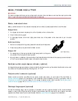
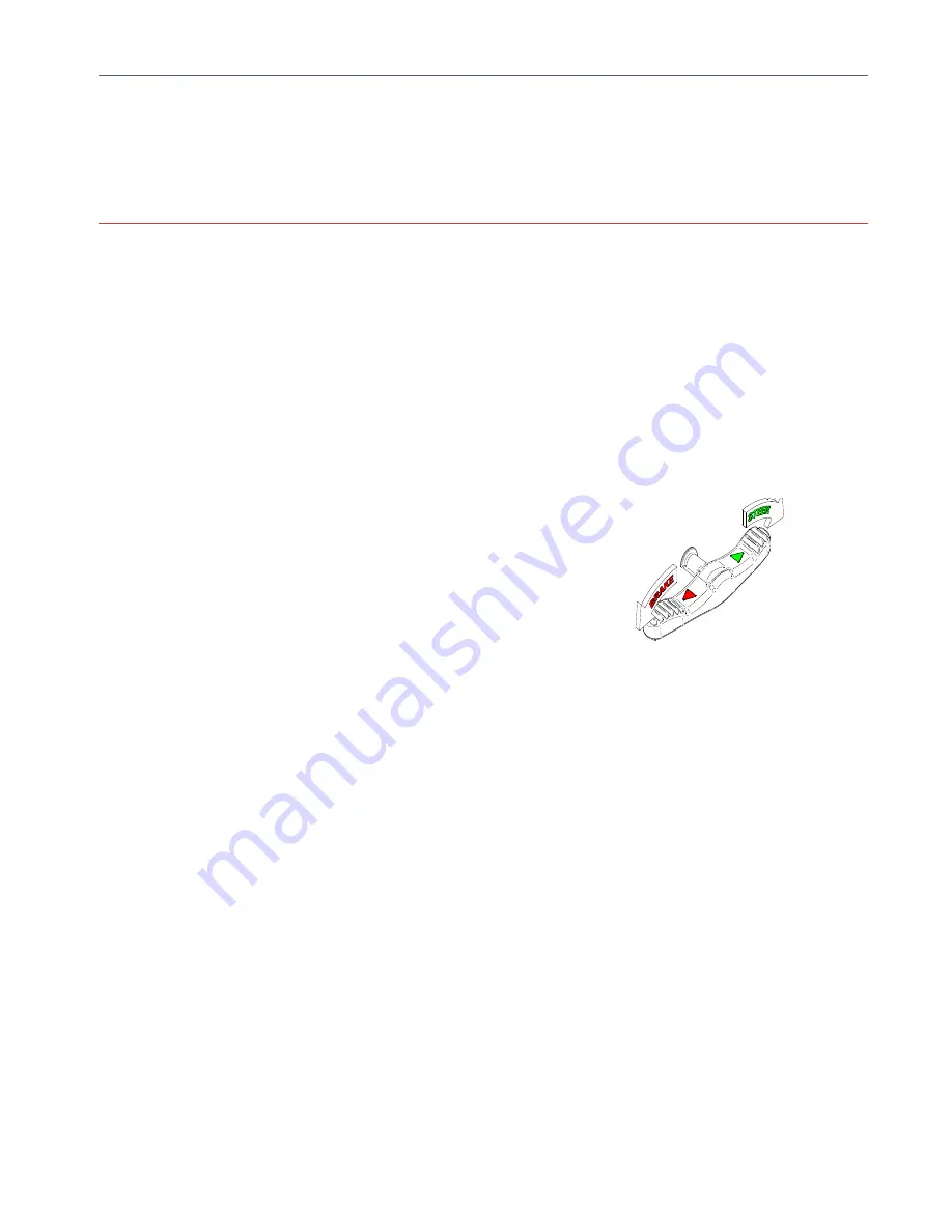
Brake, neutral and steer can be activated manually with one of the 2 pedals located at foot end of the bed.
Engage brakes:
1. To engage, press down completely one of the 2 pedals on the red arrow side.
2. Ensure brakes are engaged.
3. To disengage brakes at foot end, lightly press down one of the pedals on the steer side to put in neutral
position.
Neutral positioning:
1. Bed is in a neutral positioning when pedals at foot ends are in flat position.
2. Press down pedal on required side for brake or steer.
Engage steer:
1. To engage steer at foot end, put pedal in fully lower position on the green
arrow side of the foot pedal in lower position.
2. Move the bed on a distance of approximately 2 feet towards desired direction for the steering caster activation.
A "click" sound indicates that the caster is locked for steer motion.
Backrest section angle degree indicator (optional)
An integrated angle degree indicator is located under the backrest section, by the siderail handle and can be used
as a reference for patient positioning. Reading from -15
o
to 75
o
.
Patient control connector (optional)
Patient control connectors are offered as an option under seat section, on each side of the bed. Refer to
Product illustration
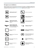
(page 6) for localization. Their localization will be indicated on bed by a picotgram; refer to
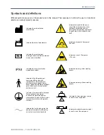
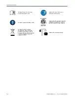
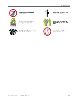
Pictograms and definitions
section (page 13). For usage of patient control, refer to section
Removable patient
control 2 functions
(page 70) or
Removable patient control 5 functions (page 71)
.
Drainage bag support (optional)
To hook the drainage bags, bed is equipped, as standard, with two supports situated on the central mattress
stopper, on each side of the seat section, and two holes situated under the foot section. As an option, four other
supports are offered under the foot end siderails. Refer to
product illustration
(page 6) for localization.
FOOT END PEDAL
Summary of Contents for ook cocoon
Page 1: ...2 0 1 7 0 8 7 4 3 6 1 0 3 E N G R 6 User manual FL36...
Page 2: ......
Page 3: ...2 0 1 7 0 8 7 4 3 6 1 0 3 E N G R 6 User manual FL36...
Page 22: ......
Page 50: ......
Page 62: ......
Page 74: ......
Page 78: ......

