ACCESSORIES
70
USER MANUAL — 74-36103-ENG R6
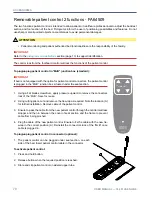
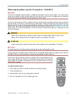
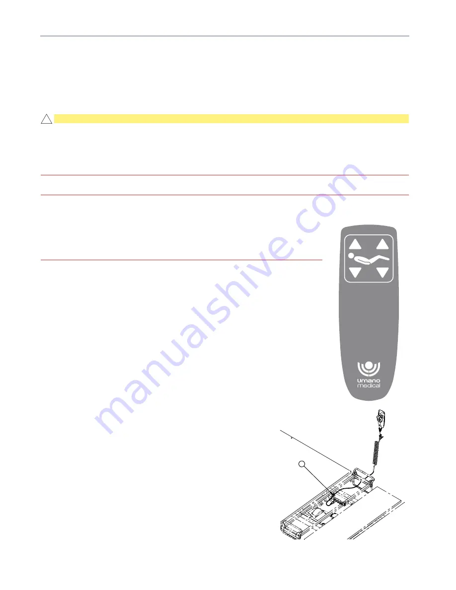
Removable patient control 2 functions - FA64509
The two functions patient control
is intended to allow patient or healthcare professionnals to adjust the backrest
section and foot section of the bed. Pictograms inform the user of positioning possibilities and features. Do not
use sharp or small pointed objects on membranes to avoid permanent damages.
ATTENTION
• Patient monitoring and patient authorized bed functionalities are the responsibility of the facility.
IMPORTANT
Refer to the
pictograms and definitions
section (page 13) to support identification.
The control lock from the footboard control will lock the functions of the patient control
To plug/unplug patient control in "MJB" junction box (standard):
IMPORTANT
If bed is not equipped with the option for patient control connectors, the patient control
is plugged in the “MJB” junction box, situated under the seat section.
1.
Using a flat blade screwdriver, apply pressure upward to remove the connectors
lock of the “MJB”. Save for reuse.
2. Using cutting pliers, cut and remove the tie wrap as required. Note the location (A)
for further installation. Remove cable of the patient control.
3. Ensure to pass the cable from the new patient control through the central mattress
stopper and then in between the cover of seat section and the frame to prevent
cable from being pinched.
4.
Plug the cable of the new patient control. Ensure to fix the cable with the new tie-
wrap in the correct position (A). Reinstall the connectors lock of the “MJB” once
cable is plugged in.
To plug/unplug patient control in connector (optional):
1. The patient control can be plugged under seat section, on each
side of the bed. Insert patient control cable in the connector.
To activate patient control:
1. Press and hold button.
2. Release button when the required position is reached.
3. Store and clip patient control on siderail upper tube.
!
A
QDF36-2152
QDF36-2180
Summary of Contents for ook cocoon
Page 1: ...2 0 1 7 0 8 7 4 3 6 1 0 3 E N G R 6 User manual FL36...
Page 2: ......
Page 3: ...2 0 1 7 0 8 7 4 3 6 1 0 3 E N G R 6 User manual FL36...
Page 22: ......
Page 50: ......
Page 62: ......
Page 74: ......
Page 78: ......

