background image

Model no

E-SM-1700-180-2H / ASIN no. B07V4CBHD7

NOTE:

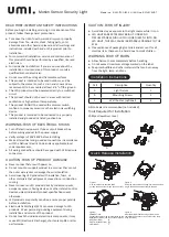
DO NOT MOUNT ON THE GROUND, RECOMMENDED 
INSTALLATION HEIGHT IS 6 ½ FEET TO 10 FEET
This product  is  intended  for use with  the enclosed gasket 

and with a junction box marked for use in wet locations.
** Before you begin make sure that your power is turned off 

at your circuit breaker box **

Do not rely on the switch power being turned off 

Install the cross bar (E) to the junction box and secure with the 
(2) mounting screws (I). If installing to a wall or building, pre-
drill holes and use appropriate plugs/anchors, once your holes 

are drilled you can install the cross bar to the surface using the 

two mounting screws (I).

1.

On the cross bar locate GND, attach the ground wire (G) 
with the grounding Screw (F) to the cross bar.

2.

Connect supply wires with wire nuts (H) as shown in the 
figure above. 

Black supply wire connects to the Black power supply wire 

(Live) 

White product wire connects to the White supply wire 

(Neutral)

3.

You may use the optional gasket (D) at this time.

4.

Install the light fixture (A) to the cross bar (E).  Use silicon 
sealant (not included) around the perimeter of the light to 

seal for moisture.

5.

Screw in the stainless steel screw (C) to hold fixture in 
place.  Insert plastic screw cover (B) into screw hole.

6.

Turn on your electricity after the install has been 

completed.

7.

Turn on power switch.  (If power switch is not on, the light 
will not cycle on or off)

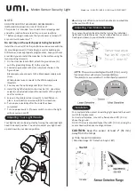
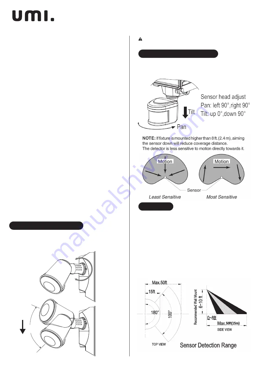
Your light heads can be adjusted by turning the individual light 

head to desired position.  You can also adjust your light head 
up and down to your desired position.

Your sensor head can be adjusted by turning the individual 

light head to detection area.  You can also adjust your sensor 

head up and down to your detection distance.

For easy installation, select an existing light operated  by a wall 

switch for replacement.

For best performance, mount the fixture about 8 ft. (2.4 m) 

above the ground. 

NOTE: If fixture is mounted higher than 8 ft. (2.4 m), aiming the 

sensor down will reduce coverage distance.

CAUTION:  

Keep  the  sensor  at  least  2”  (51 mm) 

away from the lamps.

SETTING THE MOTION SENSOR

( Detection Range: 50’  Detection Angle: 180°)   

     warning-risk of fire.Do not aim the bulbs at a combustible 

surface within 3 ft.(1m)

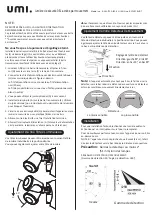
350°

60°

60°

Adjusting Your Light Heads

Adjusting Your Motion Sensor

Installation

Motion Sensor Security Light

Summary of Contents for E-SM-1700-180-2H

Page 1: ...ng pads powders steel wool or any other abrasive materials Do not immerse in water Please read all instructions thoroughly and carefully prior to installing this product Retain these instructions for...

Page 2: ...tching device This product is intended to be connected to a properly installed and grounded UL listed junction box WARNING RISK OF ELECTRICAL SHOCK Turn o electrical power at fuse or circuit breaker b...

Page 3: ...silicon sealant not included around the perimeter of the light to seal for moisture 5 Screw in the stainless steel screw C to hold xture in place Insert plastic screw cover B into screw hole 6 Turn on...

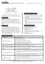
Page 4: ...54 Warm Up about 60 seconds SYMPTOM POSSIBLE CAUSE Lights will not come on 1 Light switch is turned o 2 Light is loose or burned out 3 Fuse is blown or circuit breaker is turned o 4 Daylight turno is...

Page 5: ...s r curer de poudres de laine d acier ou de tout autre mat riel abrasif Ne pas immerger dans l eau Veuillez lire attentivement toutes les instructions avant d installer ce produit Conservez ces instru...

Page 6: ...spositif de commutation lectronique Ce produit est destin tre connect une bo te de jonction UL correctement install e et mise la terre AVERTISSEMENT RISQUE DE CHOC LECTRIQUE teignez l alimentation lec...

Page 7: ...teint pas Vos t tes lumineuses peuvent tre ajust es en tournant la t te de lumi re individuelle la position d sir e Vous pouvez galement ajuster votre t te de lumi re Vos t tes de d tecteur peuvent t...

Page 8: ...POSSIBLE Les lumi res ne s allument pas 1 L interrupteur de lumi re est teint 2 La lumi re est l che ou br l e 3 Le fusible est sou ou le disjoncteur est teint 4 L extinction de la lumi re du jour est...

Page 9: ...rschw mme Pulver Stahlwolle oder andere Schleifmaterial Nicht ins Wasser eintauchen Bitte lesen Sie alle Anweisungen sorgf ltig durch bevor Sie dieses Produkt installieren Bewahren Sie diese Anleitung...

Page 10: ...chaltger t verwendet werden Dieses Produkt ist f r den Anschluss an eine ordnungsgem installierte und geerdete UL gelistete Junction Box vorgesehen WARNUNG STROMSCHLAGGEFAHR Trennen Sie die Stromverso...

Page 11: ...den Netzschalter ein Wenn der Netzschalter nicht eingeschaltet ist schaltet sich das Licht nicht wieder ein oder aus Ihre Leuchtenk pfe k nnen eingestellt werden indem Sie den einzelnen Leuchtenkopf i...

Page 12: ...cherung durchgebrannt oder Leistungsschalter ausgeschaltet 4 Die Abschaltung bei Tageslicht wirkt bei Dunkelheit wieder pr fen 5 Falsche Verdrahtung wenn es sich um eine Neuinstallation handelt 6 Rich...

Page 13: ...veri lana d acciaio o altri materiali abrasivi Non immergere in acqua Leggere attentamente e attentamente tutte le istruzioni prima di installare questo prodotto Conservare queste istruzioni per rifer...

Page 14: ...odotto deve essere collegato correttamente scatola di giunzione installata e messa a terra omologata UL ATTENZIONE RISCHIO DI SCOSSE ELETTRICHE Disattivare l alimentazione elettrica sul fusibile o sul...

Page 15: ...cceso la luce non si accende o si spegne Le loro teste luminose possono essere regolate girando la luce individuale Dirigiti nella posizione desiderata La testa del sensore pu essere regolata ruotando...

Page 16: ...i non si accenderanno 1 L interruttore della luce spento 2 La luce allentata o bruciata 3 Il fusibile bruciato o l interruttore automatico spento 4 L arresto della luce diurna attivo ricontrollare dop...

Page 17: ...opajos polvos lana de acero ni ning n otro material abrasivo No sumergir en agua Lea todas las instrucciones detenidamente y detenidamente antes de instalar este producto Conserve estas instrucciones...

Page 18: ...onexiones listada UL instalada y conectada a tierra ADVERTENCIA RIESGO DE DESCARGA EL CTRICA Apague la energ a el ctrica en la caja de fusibles o disyuntores antes de conectar el producto a la fuente...

Page 19: ...terruptor de encendido Si el interruptor de encendido no est encendido la luz no se encender o apagar Sus cabezas de luz se pueden ajustar girando la luz individual cabeza a la posici n deseada El cab...

Page 20: ...no se encender n 1 El interruptor de la luz est apagado 2 La luz est oja o quemada 3 El fusible est quemado o el disyuntor est apagado 4 El apagado de la luz del d a est en vigor vuelva a veri car de...

Reviews: