background image

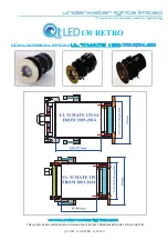
QT LED - 130 - SCREWED BULLEYT RETRO

PLEASE REGISTER YOUR PRODUCT WARRANTY DIRECT TO

WWW.REGISTER-UWL.COM

For sales telephone numbers visit www.qtled.com

THE QT-LED RANGE IS DESIGNED AND MANUFACTURED BY UNDERWATER LIGHTS LTD IN THE 

U.K.

CUTE ON SIZE - BIG ON LIGHT

For sales and information visit 

WWW.QTLED.COM

BULLEYT RETRO

underwater lights limited

Manufacturer of the Original


underwater lights


Brand

Marine Lighting Products Since 1991

TM

TM

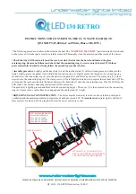
INSTRUCTIONS FOR CONVERTING THE SCREWED BULLEYT TO 

QT-130 (Standard 10,000 lm) or QT-130 HP (18,500 lm Cool White or RGB+W)

*

The following procedure is achieved from inside the hull. The 

“ EXISTING  LIGHT ”

 parts indicated below should not 

be removed. All other parts must be carefully removed. Thoroughly clean the glass lens and the inside of the barrel.

*Check that the LED heat sink (1) and the rear heat sink (2) slide into the barrel and land on the glass 
retaining ring. Remove both items and check that the connecting ring (3) screws onto the barrel. With these parts 
successfully checked for fi tting follow the assembly procedures below.

*Assembly procedure-

 Lightly coat the heat sink (1) and the rear heat sink (2) with a silicone grease and slide into the 

barrel. Screw the additional heat sink (3 + 4) onto the light barrel. The clamp ring (5) is then screwed into the back of the 
heat sink ring (3). The clamp screws (6) are lightly screwed up to compress the rear heat sink (2) onto the front heat sink 
(1). This will expand the rear heat sink into the barrel and press the heat sink (1) onto the lens retaining ring. Plug the LED 
into the PCB socket (10) See further connecting instructions for this procedure. 
Slacken the cable gland so the cable will not turn when screwing the cover (8). The cover (8) with the ‘O’ ring (9) is then 
screwed into the back of the heat sink ring (3). Ensure that no cables have been trapped and fi nally tighen the cable gland 
(7).

*DRIVER INSTALLATION INSTRUCTION

 - The driver must be located at least 60 cm above tank top with good 

ventilation and the maximum ambient temperature  should not exceed 40C. The

 standard

 underwater light is fi tted with 

three meters of cable and a IP 68 plug that fi ts into the driver enclosure socket.

1

2

3

4

5

6

7

8

9

10

11

EXISTING LIGHT

cute on size big on light

Summary of Contents for QT 40 RETRO

Page 1: ...OXPLQDWLRQ QVWDOODWLRQ UHTXLUHV QR PRGLIL FDWLRQ WR FODVV DSSURYDOV DQG IL WWLQJ WKHVH IL WXUHV FDQ WDNH DV OLWWOH DV RQH KRXU WR WRWDOO WUDQVIRUP DQ H LVWLQJ XQGHUZDWHU OLJKWLQJ VHWXS 7KH 47 5HWUR LV...

Page 2: ...FSHMBTT PBU TJ F 6Q UP FFU 6Q UP N 4QBDJOH N N QPSU TUBSCPBSE FBN OHMF OTUBMMBUJPO OHMFT MVTI Technical VNFOT GPS XIJUF FMWJO 5ZQJDBM JGF YQFDUBODZ IST JO BY 0QFSBUJOH 7PMUBHF 7 VSSFOU NQ ESBX SJWFS 5...

Page 3: ...the body When the heat sink 1 cannot be rotated the clamp ring 3 has secured all in place If this is not done it will cause overheating of the LED and the LED could fail Caution do not operate lights...

Page 4: ...nto the body When the heat sink 1 cannot be rotated the clamp ring 3 has secured all in place If this is not done it will cause overheating of the LED and the LED could fail Caution do not operate lig...

Page 5: ...QR PRGLIL FDWLRQ WR FODVV DSSURYDOV DQG IL WWLQJ WKHVH IL WXUHV FDQ WDNH DV OLWWOH DV RQH KRXU WR WRWDOO WUDQVIRUP DQ H LVWLQJ XQGHUZDWHU OLJKWLQJ VHWXS 7KH 476 5HWUR LV GHVLJQHG IRU ERDWV ZLWK WKH 2...

Page 6: ...ting VMM BUFSJBM 31 JCFSHMBTT PBU TJ F NFUFST GU 4QBDJOH N N QPSU TUBSCPBSE FBN OHMF OTUBMMBUJPO OHMFT MVTI Technical VNFOT GPS XIJUF FMWJO 5ZQJDBM JGF YQFDUBODZ IST JO BY 0QFSBUJOH 7PMUBHF 7 VSSFOU N...

Page 7: ...ng 3 has secured all in place If this is not done it will cause overheating of the LED and the LED could fail Caution do not operate lights unless totally submerged OHFWULFDO LQVWDOODWLRQ The QT6 0 re...

Page 8: ...XJUDI 5IF DPOOFDUJPO FODMPTVSF IBT B BNQ GVTF UIBU XJMM QSPUFDU UIF TVQQMZ DBCMF 8IFO ZPV IBWF NBEF UIF DPOOFDUJPOT FOTVSF UIF QPMBSJUZ JT DPSSFDU BOE TXJUDI PO UIF MJHIU GPS UFTUJOH 5IFO QSPDFFE XJUI...

Page 9: ...QTXLUH IRU GHWDLOV ZZZ XQGHUZDWHUOLJKWV FRP 7 47 5 1 6 6 1 1 0 18 785 81 5 7 5 76 7 1 7 8 7 SH 5HWUR VVXH DWH 5IF 25 3FUSP JT EFTJHOFE GPS CPBUT XJUI UIF NFUBM IBMJEF 0SJHJOBM TDSFXFE VMMFZU 6 5J 5 GJ...

Page 10: ...cal Dealer 25 1 25 3 8 MVF Technical VNFOT PU QQMJDBCMF FMWJO PU QQMJDBCMF 5ZQJDBM JGF YQFDUBODZ IST IST JO BY 0QFSBUJOH 7PMUBHF 7 7 VSSFOU NQ ESBX BNQT BNQT SJWFS 5ZQF YUFSOBM YUFSOBM SJWFS 0VUQVU 7E...

Page 11: ...47 5 752 ZZZ XQGHUZDWHUOLJKWV FRP 7 47 5 1 6 6 1 1 0 18 785 81 5 7 5 76 7 1 7 8 219 56 21 520 8 7L 0 7 72 47 5 752...

Page 12: ...UUHO VR WKH JDVNHW DQG IRUPV D JRRG VHDO 7KH FODPS ULQJ LV WKHQ VFUHZHG LQWR WKH FRQQHFWLQJ ULQJ 7KH FODPS VFUHZV DUH OLJKWO VFUHZHG XS WR FRPSUHVV WKH UHDU KHDW VLQN 7KLV ZLOO H SDQG WKH UHDU KHDW VL...

Page 13: ...checked for fitting follow the assembly procedures below Assembly procedure Lightly coat the heat sink 1 and the rear heat sink 2 with a silicone grease and slide into the barrel Screw the additional...

Reviews: