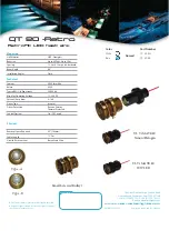
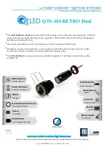
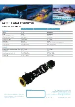
QT LED - 130 - SCREWED BULLEYT RETRO
PLEASE REGISTER YOUR PRODUCT WARRANTY DIRECT TO
WWW.REGISTER-UWL.COM
For sales telephone numbers visit www.qtled.com
THE QT-LED RANGE IS DESIGNED AND MANUFACTURED BY UNDERWATER LIGHTS LTD IN THE
U.K.
CUTE ON SIZE - BIG ON LIGHT
For sales and information visit
WWW.QTLED.COM
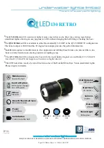
BULLEYT RETRO
underwater lights limited
Manufacturer of the Original
underwater lights
Brand
Marine Lighting Products Since 1991
TM
TM
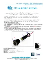
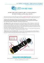
INSTRUCTIONS FOR CONVERTING THE SCREWED BULLEYT TO
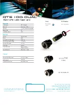
QT-130 (Standard 10,000 lm) or QT-130 HP (18,500 lm Cool White or RGB+W)
*
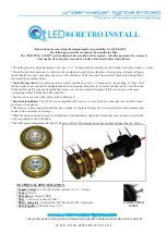
The following procedure is achieved from inside the hull. The
“ EXISTING LIGHT ”
parts indicated below should not
be removed. All other parts must be carefully removed. Thoroughly clean the glass lens and the inside of the barrel.
*Check that the LED heat sink (1) and the rear heat sink (2) slide into the barrel and land on the glass
retaining ring. Remove both items and check that the connecting ring (3) screws onto the barrel. With these parts
successfully checked for fi tting follow the assembly procedures below.
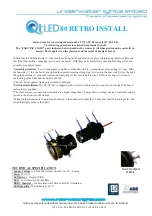
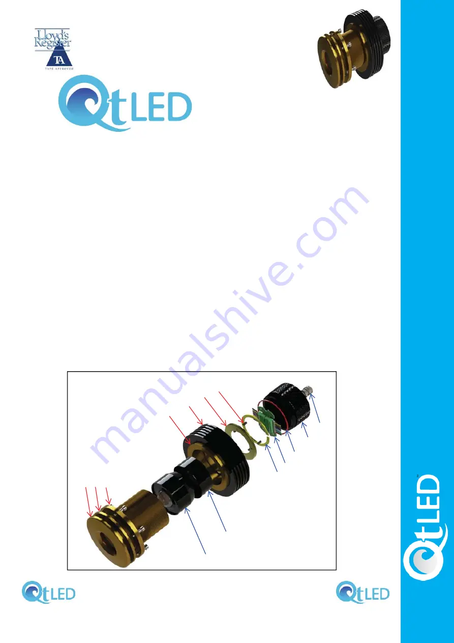
*Assembly procedure-
Lightly coat the heat sink (1) and the rear heat sink (2) with a silicone grease and slide into the
barrel. Screw the additional heat sink (3 + 4) onto the light barrel. The clamp ring (5) is then screwed into the back of the
heat sink ring (3). The clamp screws (6) are lightly screwed up to compress the rear heat sink (2) onto the front heat sink
(1). This will expand the rear heat sink into the barrel and press the heat sink (1) onto the lens retaining ring. Plug the LED
into the PCB socket (10) See further connecting instructions for this procedure.
Slacken the cable gland so the cable will not turn when screwing the cover (8). The cover (8) with the ‘O’ ring (9) is then
screwed into the back of the heat sink ring (3). Ensure that no cables have been trapped and fi nally tighen the cable gland
(7).
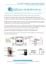
*DRIVER INSTALLATION INSTRUCTION
- The driver must be located at least 60 cm above tank top with good
ventilation and the maximum ambient temperature should not exceed 40C. The
standard
underwater light is fi tted with
three meters of cable and a IP 68 plug that fi ts into the driver enclosure socket.
1
2
3
4
5
6
7
8
9
10
11
EXISTING LIGHT
cute on size big on light