16
If the pump is blocked, contact you local
dealer for technical support.
STEP 4
• Hold pressed the button
4
. On the di-
splays
D1
and
D2
will appear “
Fan
Asp
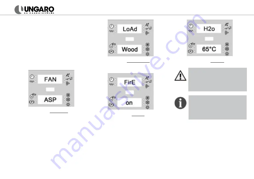
”. In this phase the thermostove
carries out the components test and
draft checking. In case of fault, may
appear the alarm codes “
No Dep
” and
“
Press H2O
”
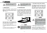
(fig. 19)
(
see chapter 8
).
fig. 19
- Test phase
• When test phase is compleated, on the
display appears
“Load Wood”
. The
pellets start to fall in the brasier and
after a few minutes the flame strikes.
fig. 20
- Pellet loading
• The following phase is “Fire On”.
fig. 21
- Fire ON
•
The flame stabilization recognizes after
appearance of the power value on the
display
D1
.
• Normally, the lowest power necessary
for the phase “
Fire On
” is
Po6
.
• On the display
D2
is shown the water
temperature. The recommended value
is
65°C
(fig. 22)
.
fig. 22
- Set H20
Faulty thermostove and flue pipe
maintenance can fault ignition during
this phase. On the display will appe-
ar “
Pull Brac
-
No Fire
”. Clean the
thermostove, empty the burning pot
and repeat the ignition.
When the ignition phase is complea-
ted, set the power to “
Po9
”. The ro-
oms will be heated in less time and
the modulation phase starts earlier.
In this way you reduce the pellet
consumption.
5.1 Logs
ignition (Bifuel model)
Open the door of the lower combustion
chamber. Place medium size logs (max
35cm length, 5 cm diameter), not more
than 1 kilo at a time. In order to avoid so-
oting on the glass, it is important that the
log is not placed adjacent to the glass on
the product.
In the wood logs combuston chamber the
temperature is controlled by motherboard.
Summary of Contents for BiFuel en ELS34
Page 1: ...USER S MANUAL...


