background image

6

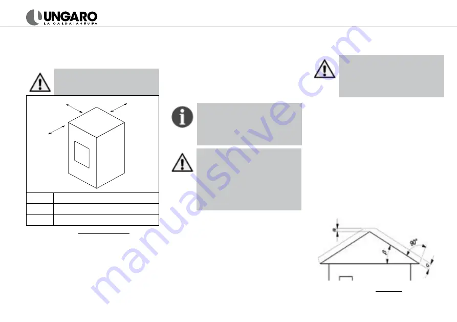
is  made  of  flammable  material,  provide  a 

floor protection surface in compliance with 

current national standards. Respect the sa-

fety clearance as shown on 

fig.1

Ungaro S.r.l. will not accept any 

liability  in  case  of  fire  for  failure  to 

comply with the safety clearance.

C

A

B

A

500 mm

B

500 mm

C

2000 mm

fig. 1 

- Safety clearance

3.4 Flue Pipe (ref. UNI 10683)

The flue pipe must meet the following re

-

quirements:

• 

Twin wall steel flue, required diame

-

ter is 100 mm round for 24 kW mo-

dels or 130 mm for 34 kW models,  

regardless of external or internal in-

stallation of the duct;

•  It must be resistant to heat, mecha-

nical stress, heat, combustion resi-

dues and related condensate;

•  It must be installed at a safe distance 

from eventual combustible materials; 

•  It must have draft between 11 and 

15 Pa.

The proper draught conditions in the 

flue  is  critical  for  the  efficient  wor

-

king of pellet boilers/thermostoves. 

All sections of the flue must be ca

-

pable of inspection and removable to 

enable periodic internal cleaning.

The boiler must be connected to a 

flue pipe or a vertical duct which can 

discharge the fumes at the highest 

point of the building, conforming to 

current national regulations. Failu-

re to comply can lead to the termi-

nation of the guarantee and of the 

manufacturer’s responsibility for the 

product.

3.5 Flue gasses discharge


To discharge the flue gas outside, make a 

hole of an adequate size to the flue pipe.

A T-element with inspection cap and 

chimney cowl 

must be installed on the 

flue pipe run. 

Maximum two accessible 90° bends are al-

lowed on the flue pipe, each of them must 

have a T-fitting with inspection cap. Maxi

-

mum permissible flue lengths are 3 meters 

with an upward slope of 3%.

Flue gasses discharge on the wall is 

not permitted by current regulations. 

Failure to comply can lead to the ter-

mination of the guarantee and of the 

manufacturer’s responsibility for the 

product.

Smoke exhaust with existing flue


A chimney cleanout access door is required. 

Control and periodically clean the chimney.

Chimney terminal position

For the installation of smoke exhaust 

ducts consult the technical regulations UNI 

10683. As shown on the 

fig.2

, the terminal  

of the chimney over the roof must have the 

following quotes (b>10°): 

- a = 500mm

- c = 1300 mm.

fig. 2 

- Chimney

Summary of Contents for BiFuel en ELS34

Page 1: ...USER S MANUAL...

Page 2: ...tion you have for high quality products To ensure safety please read this manual carefully before installation and follow the instructions herein THE TABLE OF CONTENTS 1 Introduction Pag 3 2 General w...

Page 3: ...nforming to the specifica tion given above compromises the running of your appliance and can therefore lead to the termination of the guarantee and of the manufacturer s responsibility for the pro duc...

Page 4: ...ave or pseudo sine wave The appliance must be connected to an electrical system which is equip ped with an earth conductor as laid down in directives 73 23 EEC and 93 98 EEC 2 2 Operating Warnings Pel...

Page 5: ...emain inside of the room 3 Installation The installation must be carried out by spe cialized personnel under responsibility of the person entrusted with it Ungaro S r l will not be held responsible fo...

Page 6: ...nnected to a flue pipe or a vertical duct which can discharge the fumes at the highest point of the building conforming to current national regulations Failu re to comply can lead to the termi nation...

Page 7: ...the vertical section of the chimney inspection insulated outdoor section initial section fig 4 Outdoor Chimney Existing flue fig 5 At the base of the flue is advisable to install a hermitically seale...

Page 8: ...te from inside and outside fig 8 The air intake must Be in the installation room Be drown outside with a special con nection wood The exit outside must be protected with a metal grate Be un obstructed...

Page 9: ...water flow external filling heating system flow and return max 1 5 Bar A flow restrictor and filling hose are installed on the DHW kit FL P2 P1 heating system pump P2 three way valve FL flow sensor P...

Page 10: ...ard manages the temperature set in the tank Contact the Technical Support in your area to activate the configura tion with buffer tank For the buffer tank settings see the chapter Thermostat Settings...

Page 11: ...ic hot water is being used If it lights up even in heating mode please contact technical support Turn the thermostove on and off with the key 4 Access with the key 3 to program ming functions Use the...

Page 12: ...be kept within certain limits Please consult local regulations and direc tives 4 4 Remote control Ungaro offers a remote control as standard for easy operation of the thermostove fig 15 Press two keys...

Page 13: ...e 10 minutes interval Press the key 3 to select the next parameter UT07 g Choose the day of the week with the key 1 With the key 2 enable ON or disable OFF the day of the week for the ignition of the...

Page 14: ...d ignition On off for days from 1 to 7 UT14 Setting fourth ignition From 00 00 to 23 50 10 minutes lag UT15 Setting fourth ignition From 00 00 to 23 50 10 minutes lag UT16 Setting days of week for fou...

Page 15: ...the key 2 On the display D1 will ap pear the current water pressure for example 1 0b The recom mended pressure in cold mode is between 0 8 and 1 2 Bar fig 17 fig 17 Pressure In the model Bi Fuel the w...

Page 16: ...ry for the phase Fire On is Po6 On the display D2 is shown the water temperature The recommended value is 65 C fig 22 fig 22 Set H20 Faulty thermostove and flue pipe maintenance can fault ignition dur...

Page 17: ...mperature in the thermosto ve falls under 5 C the circulation pump ac tivates to prevent system freezing 6 3 Regulation of pellet and air feeding If the combustion is not regular for exam ple Unburnt...

Page 18: ...f the fuel the more frequently will intervention be neces sary for cleaning Protect the floor from ash before cleaning the thermostove fig 24 Ash tray To prevent the ash falling during cleaning enable...

Page 19: ...ce a day when the thermostove is cold fig 27 Exchanger cleaning Regular exchanger cleaning helps to keep high efficiency of the thermo stove 7 4 Ash Box Cleaning Empty the ash box fig 28 when it is fu...

Page 20: ...ervice Annually contact the local Technical Support to perform annual service and to check up the following components Door gaskets Ash box gaskets Exchanger gaskets Tube bundle silicone gaskets T ins...

Page 21: ...days When full or dirty Each year Burning Pot Exchanger Ash Box Inspection Compartment Glass Ceramic Fiber Gaskets Gaskets Internal Flue Pipeline Pump Plate Heat Exchanger Main Components Thermostove...

Page 22: ...r temperatu re if Zoned heating system doesn t have an open zone to dissipate the produ ced heat Circulation pump is blocked Shut off valves are closed If domestic hot water kit is installed and the l...

Page 23: ...e power cable remove the inspection box and check if there is a foreigh object in the exhaust extraction fan Contact Customer Support ALARM HOT PELL High temperature in the pellet hopper Faulty securi...

Page 24: ...ermostato Terra flash Trasduttore PRP 300 IMIT 230 V Ventola fumi M M Coclea M Ventola aria P Resistenza accensione Pompa Circuito di Riscaldamento Valvola deviatrice Fase Neutro ALD ALP ALA Bianco Ma...

Page 25: ...230Vac 50Hz CN9 18 19 Klikson Fluxostat 5 Volt CC 40 GND 5V 5 Volt CC 41 Encoder Encoder 5 Volt CC 42 5V Low tension power fluxostat encoder pressure transducer 5 Volt CC CN7 20 21 S FUMI Exhaust gas...

Page 26: ...as mass flow rate g s 20 1 fig 34 Serial Number 11 After Sale Service For any information or problem please contact your dealer 11 1 Richiesta d intervento Please read this manual carefully before ask...

Page 27: ...will give 1 Service Log signed 2 Invoice for the used spare parts for out of warranty interventions UNGARO S r l ricorda che il costrut tore titolare dei diritti previsti dal D lgs 206 2005 e che la s...

Page 28: ...28 860 920 600 600 80 130 83 113 208 65 115 65 148 Uscita fumi Mandata impianto 3 4 Calda sanitaria 1 2 Fredda sanitaria 1 2 Ritorno impianto 3 4 Entrata Aria Kucina...

Page 29: ...60 397 346 65 115 65 203 360 190 935 795 60 175 560 795 80 180 Mandata impianto 3 4 Calda sanitaria 1 2 Fredda sanitaria 1 2 Ritorno impianto 3 4 Entrata aria pellet Entrata aria legna Uscita fumi leg...

Page 30: ...c glass painted fini shes and other external finishes The Customer is in charge of eventual costs re pair transport arising from improper exercise of warranty rights Ungaro S r l is not responsible fo...

Page 31: ...nd make such data available to a data pro cessor under the terms and conditions set out by the Personal Data Protection Act I acknowledge my right to access the personal data edit it and to withdraw t...

Page 32: ...0 SAN MANGO D AQUINO CZ Italy Tel 39 0968 926838 Tel 39 0968 96484 Fax 39 0968 926635 www caldoungaro it Under no circumstances shall Ungaro S r l assume liability for imprecise contents or eventual e...

Reviews: