Quality Tools for Smart Cleaning
www.ungerglobal.com/hydropower
D
E
F
F2
G
H
12
Hydropower dI
Resin Change
6. Resin Change
6.1 Capacity
Since the DI resin filter is used at different filling points with various degrees of
hardness, the available quantity of completely desalinated water differs.
The conductivity measurement is used to monitor water quality.
If a conductivity measurement indicates a value of > 10 ppm, the resin is depleted.
The QuickChange resin bag or the loose resin must be replaced.
Raw water quality can be determined in various ways.
a) Information from responsible water works (indication of overall hardness).
b) By measuring the mineral content with Unger TDS-Meter
(5)
.
6.2 Resin Change - QuickChange resin bags
Unger’s pre-measured replacement QuickChange resin bags are designed
to allow a controlled resin expansion within a designed safety limit.
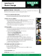
1. SHUT OFF TAP WATER SUPPLY VALVE
a. Shut off tap water supply and open pole tubing discharge line.
b. Disconnect feed tap water line and allow system to drain.
2. REMOVE TOP CAP ASSEMBLY:
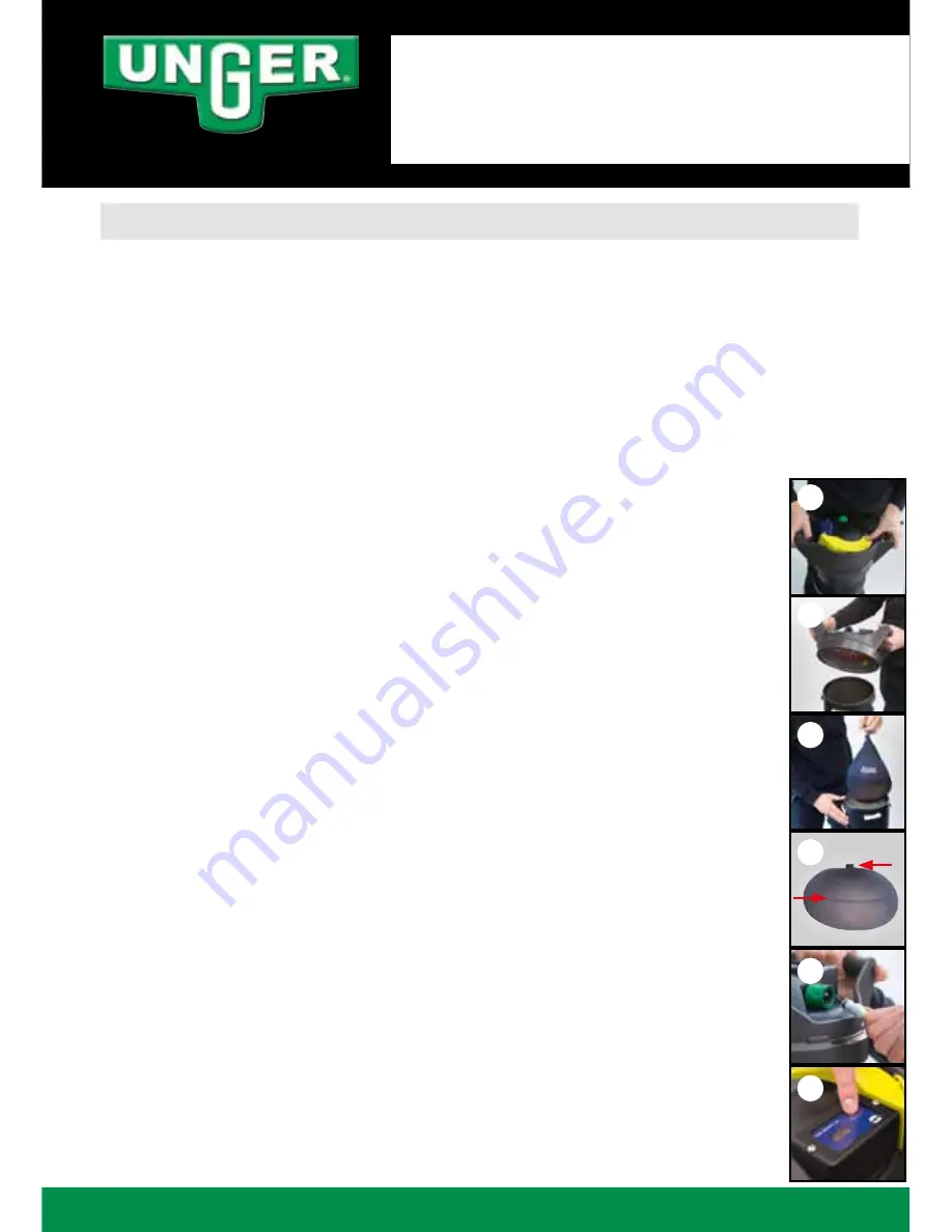
a. Press yellow FastLock Opening lever
(3)
(fig. D) to to get pressure
out of the vessel, fix the base unit with your feet, press the top cap
slightly down and use a counter-clockwise 1/8 turn to release top cap
assembly; remove and set aside (fig. E).
b. Open all valves to facilitate the removal of the bags.
c. Reach into housing and remove exhausted resin bag(s) by hand (fig. F);
discard according to local regulations.
3. REPLACE RESIN BAG
a. Install new resin bag(s) by hand (fig. F) – be sure to seat bags with
zip-tie facing up and sewing in parallel to vessel ledge (fig. F2).
Otherwise resin capacity will not completely be used and ppm value is
too high.
b. Inspect system head assembly: O-ring and FloWater distribution
filter are in good condition. Re-coat o-ring with silicone lubricant only.
c. Re-install DI System head assembly, press it slightly, then turn it 1/8
clockwise while fixing the base unit with your feet.
d. System is ready to be operated.
4. RECONNECT WATERFED POLE TUBING
(fig. G)
a. Turn “ON“ water supply at tap.
b. Inspect system as it pressurizes.
c. Keep discharge line open and hold down yellow lever
(3)
to remove
trapped air from system.
5. TEST SYSTEM TDS
(fig. H)


