www.ungerglobal.com
www.ungerglobal.com
Unger‘s pre-measured replacement Ultra Resin Packs are designed to allow
a controlled resin expansion within a designed safety limit.
1. SHUT OFF FEED WATER SUPPLY
• Depress yellow lever on system head assembly.
• Turn tap water valve to “OFF” position.
• Disconnect waterfed wash pole hose.
2. RELEASE SYSTEM HEAD ASSEMBLY
• While continuing to depress the yellow lever, use a counter-clockwise
quarter‐turn to release system head assembly; remove and set aside.
• Reach into housing and remove exhausted resin by hand; discard
according to local regulations.
• Press yellow FastLock opening lever (fig.
E
) to remove pressure from
the tank.
• Steady (or “Stabilize”) the base unit with your feet, gently press the top
cap down and use a counter-clockwise 1/8 turn to release top cap
assembly; remove and set aside (fig.
F
).
• Open all valves to facilitate the removal of the Ultra Resin Packs.
• Reach into housing and remove exhausted Ultra Resin Pack(s) by hand
with the rubber handle (fig.
G
); discard according to local regulation
System Overview
System Setup
D
H
A
E
I
B
F
J
C
G
K
L
Resin Change
2
3
21064
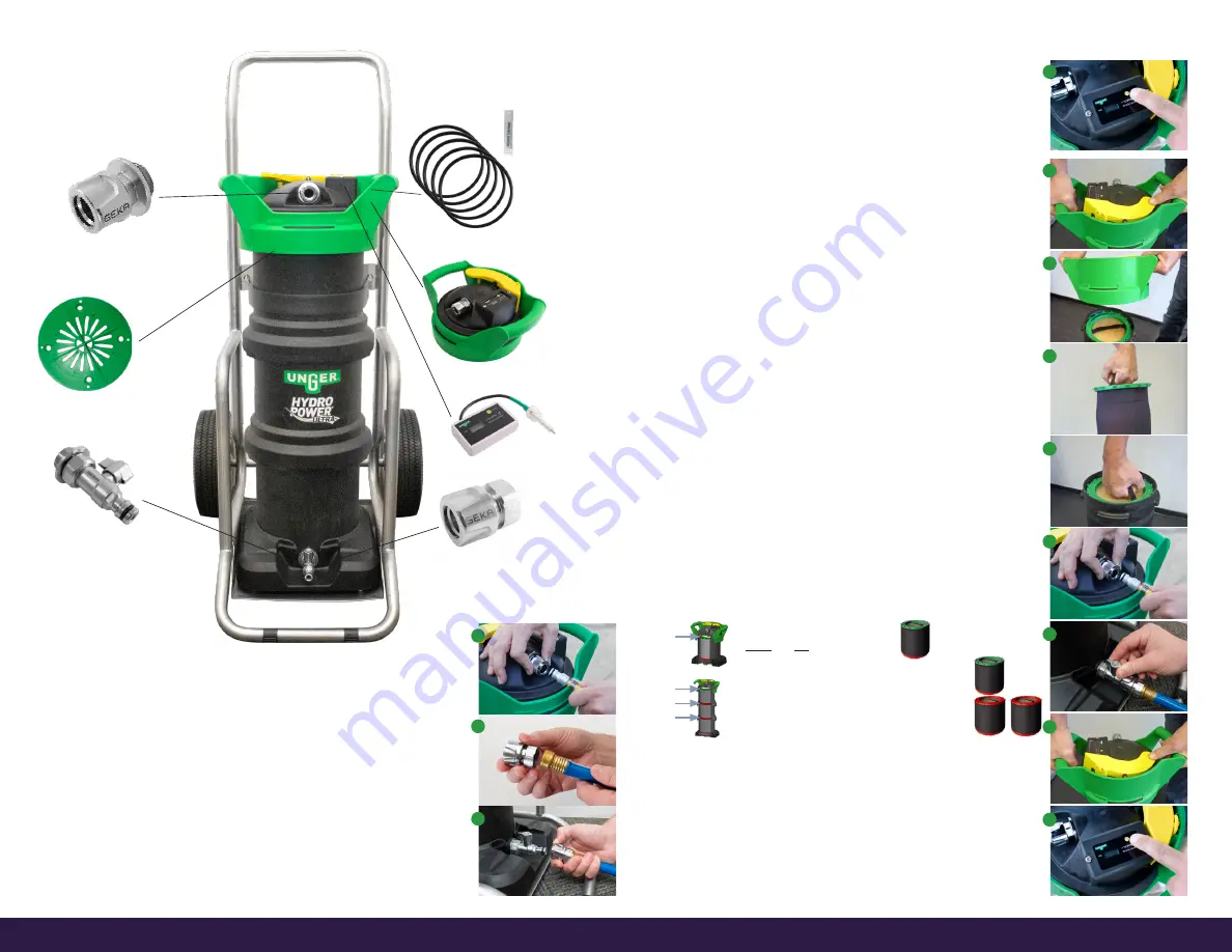
Water OUT Connection with
O-Ring
21063
O-Rings (5), Care Resolution
21071
Top Cap Assembly
21151
TDS Meter
21504
Water IN Hose Connection
21066
FloWater
™
Unit
21065
Water IN On/Off Connection
4. TURN ON FEED WATER SUPPLY
• When water begins to flow out of the unit, turn on TDS meter and
inspect pure water quality (fig.
D
). A reading of ‘0’ is best and indicates
the system is running properly. When the TDS meter reaches 10ppm or
higher the resin should be replaced.
• Adjust flow at waterfed pole brush head by:
- Tap water valve or,
- Waterfed wash pole control (on/off) valve (if applicable).
1. LOCATE JOBSITE WATER SUPPLY
Unger recommends testing the on‐site water supply for TDS (total dissolved solids)
prior to working. Higher TDS levels reduce the system’s capacity.
• Inspect system – ensure Unger‘s Ultra Resin Packs are properly installed: the
red Resin Pack is only used on a 3-stage unit and placed in the middle and
bottom position. The green Resin Pack is used in all units and is placed in the top
position. NOTE: The performance of HydroPower Ultra is optimized when used
with Ultra Resin Packs. NEVER use loose resin as it may damage the system.
• Set up system in upright position.
• Choose a stable on‐site location.
2. CONNECT WATERFED WASH POLE TUBING
• Attach waterfed wash pole hose onto Water OUT connection (fig.
A
).
• Ensure all on/off valves are in “OPEN” position when filling system.
3. CONNECT WATER SUPPLY (GARDEN HOSE) TO WATER IN CONNECTION
• Thread On/Off Valve to garden hose prior to connecting water supply (fig.
B
).
• Attach On/Off Valve directly onto Water IN connection at base of unit (fig.
C
).
3. REPLACE ULTRA RESIN PACKS
• Install new Ultra Resin Packs (fig.
H
) – be sure to seat the packs with
rubber handle facing up. Pat down the pack by hand to ensure it is
seated properly.
Small tank unit (UHP01)
:
= 1x green Ultra Resin Pack
(never use red Ultra Resin Pack
in this unit!)
Large tank unit (UHP3C)
:
= 1x green Ultra Resin Pack (top position)
2x red Ultra Resin Packs ( bottom position)
green
red
red
green
4. REINSTALL TOP CAP ASSEMBLY
• Press down gently, then turn the top cap 1/8 clockwise while
steadying the base unit with your feet.
5. RECONNECT WATERFED POLE TUBING
(fig.
I
)
• Turn “ONˮ water supply at tap (fig.
J
).
• Inspect system as it pressurizes.
• Keep discharge line open and hold down yellow lever to remove
trapped air from system (fig.
K
).
6. TEST SYSTEM TDS
(fig.
L
) The value should be at
000
.


