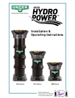
Installation &
Operating Instructions
12
Operation
1. Periodically inspect the HydroPower system during use. Ensure hoses are
properly attached. Inspect system for leaks and proper fit of top cap assembly.
2. Take care when working to ensure there is enough slack in waterfed wash pole
tubing. This tubing is connected to the top of the unit, and excessive tugging
may cause the system to tip over.
3. Drinking water flows into the system’s lower connection port via tap pressure
and flows upwards through the HydroPower tank. Pure Water exits through the
top connection. When plumbing line pressures fall below 40psi, a reduction in
flow rates will be noticeable.
4. The on/off valve can be used to adjust water flow rates coming out of the
waterfed wash pole brush jets. Excessive flow from the brush head jets can
cause water splattering from uncleaned glass back onto previously cleaned
areas, resulting in spotting.
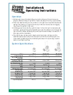
System Specifications
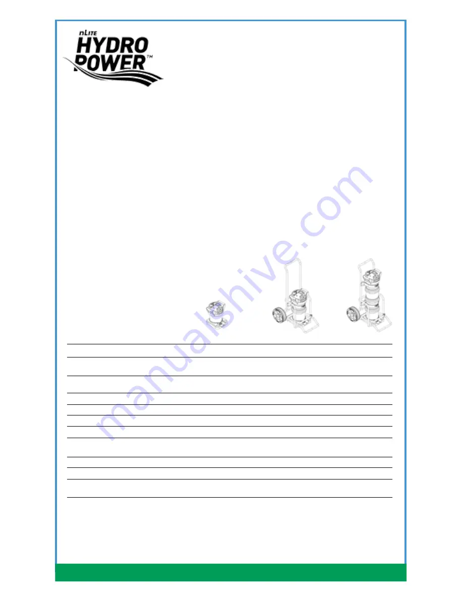
Model
HP06T HP12T/HP12C HP24T/HP24C
DI Resin Capacity
6.0l/0.21 cu. ft.
12.0l/0.42 cu. ft.
24l/0.84 cu. ft.
Qty. of HPB Resin Bags
1 2 4
per system
Pure Water Production
300 gal./1125l
600 gal./2250l
1200 gal./4500l
(100 TDS Incoming/; 0 TDS output)
No. of Poles Rated for Use
1 pole
1-2 poles
1-2 poles
Power
Tap Pressure
Tap Pressure
Tap Pressure
Pump
NA
NA
NA
Working Hose Length
100 ft./30m plus
100 ft./30m plus
100 ft./30m plus
Working Height
3 to 5
5 to 6
5 to 6
Building Stories
tap: 60 psi/4 bar
tap: 60 psi/4 bar
tap: 60 psi/4 bar
Pure Water Flow
1.5 gpm/6 lpm
1.5 gpm/6 lpm
1.5 gpm/6 lpm
Gallons Per Day
1200 gal./4500l
1200 gal./4500l
1200 gal./4500l
System Capacity
300 gal./1125l
600 gal./2250l
1200 gal./4500l
Before Service
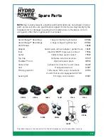
System Components
DI Resin
DI Resin
DI Resin

