background image

37

UNI-FLAME 

UNI-FLAME

 AUTOLIFT

Suregrip Series

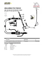
SR26 ERGO TIG TORCH

©All rights reserved. No part of this publication may be reproduced, stored in a retrieval system or transmitted by any means,

electronic, mechanical, photocopying or otherwise without the prior permission of ©Uniarc® the copyright holder.

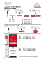
Standard Front End Parts

Part #  Description

18CG 

Cup Gasket

Part # 

Description

10N22 

Collet 1.0mm

10N23 

Collet 1.6mm

10N24 

Collet 2.4mm

10N25 

Collet 3.2mm

Part # 

Description

10N30 

Collet Body 1.0mm

10N31 

Collet Body 1.6mm

10N32 

Collet Body 2.4mm

10N28 

Collet Body 3.2mm

Part # 

Description

10N50 

Alumina Nozzle  

Ø  

6mm   #4

10N49 

Alumina Nozzle  

Ø  

8mm   #5

10N48 

Alumina Nozzle  

Ø  

10mm   #6

10N47 

Alumina Nozzle  

Ø  

11mm   #7

10N46 

Alumina Nozzle  

Ø  

13mm   #8

10N45 

Alumina Nozzle  

Ø  16

mm   #10

10N44 

Alumina Nozzle  

Ø  

19mm  #12

Part # 

Description

10N49L  Long Alumina Nozzle Ø 

8mm   #5L

53N48L  Long Alumina Nozzle Ø  

10mm  #6L

53N47L  Long Alumina Nozzle Ø  

11mm  #7L

Part # 

Description

54N01 

Gas Lens Gasket

Part # 

Description

45V25 

Gas Lens Body 1.6mm

45V26 

Gas Lens Body 2.4mm

45V27 

Gas Lens Body 3.2mm

Part # 

Description

54N14 

Gas lens ceramic 8.0mm 

54N15 

Gas lens ceramic 7.0mm 

54N17 

Gas lens ceramic  5.0mm 

Compact Gas Lens Front End Parts

Part # 

Description

TR0004-10 

1.0mm x 175mm thoriated tungsten electrode 2%

TR0004-16 

1.6mm x 175mm thoriated tungsten electrode 2%  

TR0004-24 

2.4mm x 175mm thoriated tungsten electrode 2%

TR0004-32 

3.2mm x 175mm thoriated tungsten electrode 2%

Part # 

Description

TR0006-10 

1.0mm x 175mm zirconiated tungsten electrode 1%

TR0006-16 

1.6mm x 175mm zirconiated tungsten electrode 1% 

TR0006-24 

2.4mm x 175mm zirconiated tungsten electrode 1%

TR0006-32 

3.2mm x 175mm zirconiated tungsten electrode 1%

TR0004-16

RED

ANSI/AWS A5.12-98

ISO 6848 WT20

2% Thoriated:

 Best stability 

at medium currents, good arc 

starts, medium tendency to spit, 

medium erosion rate.  

Commonly used for steel and 

stainless steel applications

1/16 x 7” (1.6mm x 175mm)

3/32 x 7” (2.4mm x 175mm)

1/8 x 7” (3.2mm x 175mm)


WHITE

ANSI/AWS A5.12 M-98

ISO 6848 WZ8

.8% Zirconiated:

 Balls well, 

handles higher current with less 

spitting, better arc starts and arc 

stability than pure tungsten

Commonly used for  

aluminium applications

1/16 x 7” (1.6mm x 175mm)

3/32 x 7” (2.4mm x 175mm)

1/8 x 7” (3.2mm x 175mm)

TR0006-16

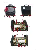
Spare Parts Identification

37

36

35

33

1

2

3
4

6

7

8

10

11 12 13

9

5

14

16

17

15

18

20

21

19

22

23

31

30

27 28

29

32

26

24

25

34

38

39

40

Summary of Contents for KUMJR200AC/DC

Page 1: ...MIG M Lift Arc D Plasma YEARS Warranty Power Source 2 Please read and understand this instruction manual carefully before the installation and operation of this equipment OPERATING MANUAL KUMJR200AC...

Page 2: ...econdly they provide a customer support service that is second to none thus ensuring our customers have confidence that they will be well satisfied both now and in the future UNI MIG welders are manuf...

Page 3: ...MMA Stick Welding 16 17 Installation Operation for DC TIG Welding 18 19 DC TIG Welding DC Pulse TIG Welding 20 22 TIG Welding Fusion and Filler Wire Technique 23 Installation Operation for AC TIG Wel...

Page 4: ...rotected from hot metal and sparks Frequently inspect input power cable for wear and tear replace the cable immediately if damaged bare wiring is dangerous and can kill Do not use damaged under sized...

Page 5: ...explode Because gas cylinders are normally part of the welding process be sure to treat them carefully CYLINDERS can explode if damaged Protect gas cylinders from excessive heat mechanical shocks phy...

Page 6: ...emperature inside the equipment The machine will be ready for use again when the internal temperature reaches safe level 2 3 Over Voltage Supply Regarding the power supply voltage range of the machine...

Page 7: ...ntamination of the tungsten electrode The Down Slope and Post Gas combined with the 2 4T trigger function gives you control of the welder allowing you to control the start and finish of the weld proce...

Page 8: ...ial Thermal Alarm LED Function Alarm LED Amperage Display Negative Output Terminal Pulse Selector AC DC Selector 2T 4T Selector TIG MMA Selector ON OFF Switch Remote Control Selector Positive Output T...

Page 9: ...the torch switch gives arc ignition and initializes the welding current 2 Releasing the torch switch continues the welding operation 3 Pressing the torch switch introduces down slope and current falls...

Page 10: ...mps during each pulse cycle Adjustment range 20 90 D Down Slope Provides adjustment of the down slope time at the end of the welding cycle At the end of the weld cycle the welding current will reduce...

Page 11: ...ideal because the nature of the AC output assists in breaking the surface oxide layer The AC Balance dial is for adjusting the current flow time between positive and negative When set at the middle t...

Page 12: ...utes 5 If there is a gas loss then check all connectors and clamps for leakage by brushing orspraying with soapy water bubbles will appear at the leakage point 6 Tighten clamps or fittings to eliminat...

Page 13: ...achine For MMA welding the electrode holder is shown be connected to the positive socket while the earth lead work piece is connected to the negative socket this is known as DC polarity However variou...

Page 14: ...t an even speed to create and even weld deposition 7 To finish the weld break the arc by quickly snapping the electrode away from the work piece 8 Wait for the weld to cool and carefully chip away the...

Page 15: ...sferred across the arc into the molten pool and becomes the deposited weld metal The deposit is covered and protected by a slag which comes from the electrode coating The arc and the immediate area ar...

Page 16: ...length no greater than the diameter of the core wire Electrode Angle The angle that the electrode makes with the work is important to ensure a smooth even transfer of metal When welding in down hand...

Page 17: ...the positive terminal and tighten it 6 Connect the torch switch remote lead into the torch remote socket 4 Insert the torch gas connector into the quick lock gas receptacle 4 Connect gas line to Gas...

Page 18: ...eleasing the torch switch continues the welding operation 3 Pressing the torch switch and holding introduces down slope and current falls to minimum current 4 Releasing the torch switch terminates the...

Page 19: ...lding offers the user the greatest amount of flexibility to weld the widest range of material and thickness and types DC TIG welding is also the cleanest weld with no sparks or spatter HF ARC IGNITION...

Page 20: ...ground Amps is a percentage of peak amperage As a rule use enough background cur rent to reduce the weld pool to about half its normal size while still keeping the weld pool fluid As a guide start by...

Page 21: ...ency around 2Hz pulses per second 5 Set the Pulse Width around 50 the current will be 50 at Peak Current and 50 at Base Current Time 1 second 110A 33A 33A 33A 50 110A 50 Peak Current Base Current On T...

Page 22: ...pool Travel direction Angle torch Add Tig filler wire Retract the filler wire Move the torch forward to the front of the weld pool Repeat the process gas shield TIG Welding Fusion Technique Manual TIG...

Page 23: ...the quick lock gas receptacle 8 Connect gas line to Gas Regulator and connect the gas regulator to the Gas Cylinder Carefully open the valve of the gas cylinder set the flow to 8 12 l min 1 Turn on t...

Page 24: ...zes the welding current 2 Releasing the torch switch continues the welding operation 3 Pressing the torch switch and holding introduces down slope and current falls to minimum current 4 Releasing the...

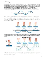
Page 25: ...cally occur during the transition between and cycles The current is less 30 during the half of the cycle when the electrode is positive and there is a resist ance of the electron flow during this half...

Page 26: ...ntrol dial on the welding machine More current flow from the direct polarity produces stronger arc energy and cur rent flow from the tungsten and is good for removing the oxidized surface of the work...

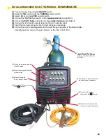
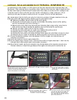
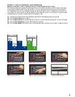
Page 27: ...u acquire a better understanding of how each variable affects the welding current 1 Prepare the machine for AC TIG welding as per the AC TIG operating guide on page 23 2 Set the Peak Current at 150 Am...

Page 28: ...peration of the remote hand control 2 Connect the remote control 7 pin plug from the Tig Torch switch lead to the 7 pin remote receptacle on the front panel of the machine 3 Press the switch to activa...

Page 29: ...or its use Ceriated Color Code Orange Ceriated tungsten electrodes AWS classification EWCe 2 contain a minimum of 97 30 percent tungsten and 1 80 to 2 20 percent cerium and are referred to as 2 percen...

Page 30: ...running lengthwise and thus grinding crosswise is grinding against the grain If electrodes are ground crosswise the electrons have to jump across the grinding marks and the arc can start before the ti...

Page 31: ...always follow standard safety guide lines when operating high speed grinding equipment Wear approved safety glasses No loose clothing which may get caught in moving parts Wear protective hair coverin...

Page 32: ...oose a larger electrode Poor welding technique Use the correct welding technique or seek assistance for the correct technique Poor joint preparation Check the joint design and fit up make sure the mat...

Page 33: ...s for holes leaks etc Moisture on the base metal Remove all moisture from base metal before welding Contaminated base metal Remove materials like paint grease oil and dirt including mill scale from ba...

Page 34: ...ten being used Check and change the size and or the tungsten if required Excessive rectification in the base metal Increase balance control Increase travel speed Add filler wire during welding Contami...

Page 35: ...umber Description 1 WP26 Torch head WP26F Torch head flexible WP18 Torch head water cooled 3 57Y02 Back cap long 3a 57Y03 Medium back cap 3b 57Y04 Short back cap 8 HWP17 Torch handle 200A AIR COOLED T...

Page 36: ...m 45V27 Gas Lens Body 3 2mm Part Description 54N14 Gas lens ceramic 8 0mm 54N15 Gas lens ceramic 7 0mm 54N17 Gas lens ceramic 5 0mm Compact Gas Lens Front End Parts Part Description TR0004 10 1 0mm x...

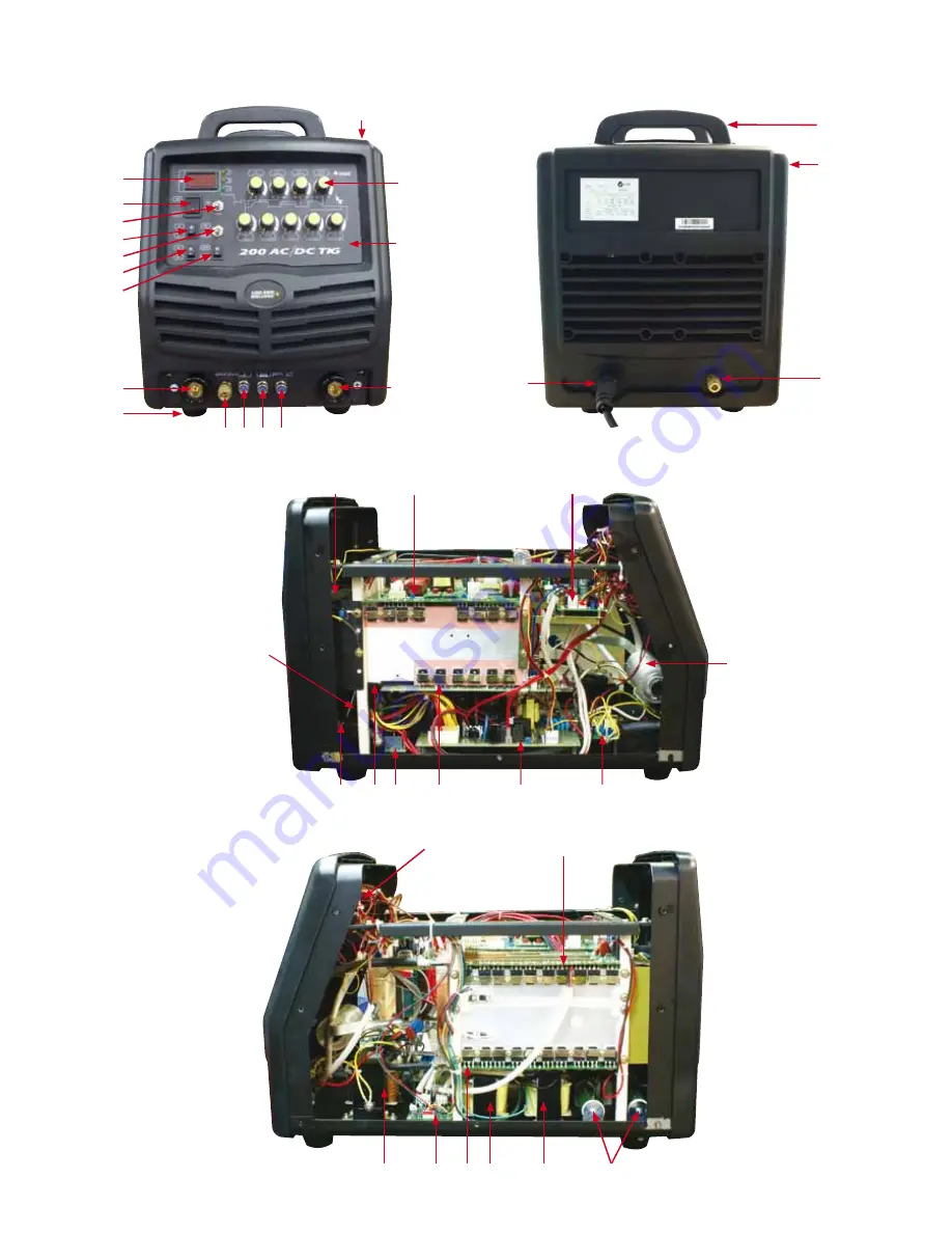
Page 37: ...37 Spare Parts Identification 37 36 35 33 1 2 3 4 6 7 8 10 11 12 13 9 5 14 16 17 15 18 20 21 19 22 23 31 30 27 28 29 32 26 24 25 34 38 39 40...

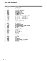
Page 38: ...0706 Front Panel Adhesive Sticker 17 C02066 Panel Socket 35 50 18 J24020 Handle 19 J06260 Rear Plastic Panel 20 C13010 Cable Support Assembly 21 J21050 Gas Connector Quick Fit Female Panel Mount 22 B0...

Page 39: ...ARRANTY RETURNS EXCHANGES 1 Subject to the conditions of warranty set out in warranty period Welding Guns Of Australia PTY LTD warrants that if any defect in any work manship of Welding Guns Of Austra...

Page 40: ...on factors such as the nature of the product and the price Welding Guns Of Australia PTY LTD adopts the same approach As you can appreciate the type of remedy we can offer you may also vary depending...

Page 41: ...112 Christina Rd Villawood NSW 2163 Phone 02 9780 4200 Fax 02 9780 4244 Email sales unimig com au Web www unimig com au Welding Guns Of Australia Pty Ltd ABN 14 001 804 422 UNI FLAME UNI FLAME AUTOLI...

Reviews: