


17
MANUAL - SPRAY GUN CLEANERS - UG5000W SERIES
Revision 2019-3
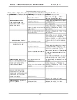
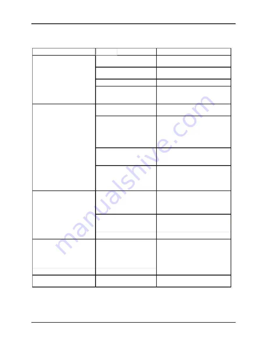
TROUBLESHOOTI
NG CHART
PROBLEM
REASON
CORRECTIVE ACTION
Drain valve closed
Open drain valve (put in vertical
position), if not already open
Liquid level too low
Check wash liquid level. Add liquid if
less than1/2 full.
Fill to 4 gal (11 L).
Debris in pump or suction and
output hose
Follow Procedure 1, "Blocked Fluid
Passage in Diaphragm pump" in the
next section.
Water or contaminants are in
air line of pump.
Passage in Diaphragm Pump" in the
next section.
Flow Control is closed.
Manual flow control is located on the
control panel on the front of the
machine. Loosen the locking nut and
rotate control to the left to increase
flow.
Liquid level too low
Check wash liquid level. Add liquid if
less than 1/2 full up to 4 gal (11 L).
Foot pedal switch not
functioning
Inspect foot switch for free travel, and
lubricate with gun oil. If switch will
not travel freely, replace with PN 155-
400BF2
Water in air line causes pump
to stall
Follow Procedure 2. "Blocked Air
Passage in Diaphragm Pump" in the
next section.
WASH PUMP DOES NOT
STOP UNLESS TIMER IS
TURNED BY HAND OR AIR IS
SHUT OFF. WASH PUMP
DOES NOT START.
Defective Timer
TIMER KNOB
SPINS BACK
WHEN TURNED
Defective Timer
Replace Timer. PN 115-200K.
Replace Timer, PN 115-200K.
WASH PUMP
MAKES
HISSING SOUND AND LIQUID
DOES NOT FLOW
BRUSH PUMP
DOES NOT
MAKE A NOISE AND LIQUID
DOES NOT FLOW WITH
PEDAL DEPRESSED
Brush is clogged with debris.
Unthread brush from hose and
operate foot pedal. If free solvent flow
is now seen, replace brush with PN
144-390S
WASH PUMP
MAKES
PUMPING SOUND BUT
LIQUID DOES NOT FLOW
FROM THE JETS
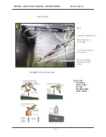
of fresh solvent. Top up clean solvent pail to 19 L. Insert the Rinse Pump into the full clean
solvent pail. Return hoses to the Wash Pail and return both pails to the cabinet.