


MANUAL - SPRAY GUN CLEANERS - UG5000W SERIES
Revision 2019-3
6
If any item is missing, contact your supplier.
Position in a well-ventilated area away from sparks, heat and
open flames.
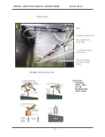
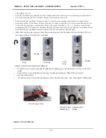
LOCATION
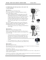
GROUND WIRES
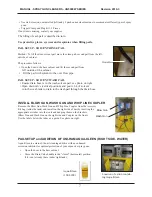
Connect the green ground wire (right side of cabinet) to a
grounded object in the facility using the ring terminal.
Note: The pump and metal tube that inserts into each
pail are bonded.
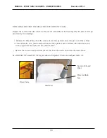
DOOR HANDLES
The cabinet has 4 doors. The 4 door handles are located on the inside of each door for shipping pur-
poses. Re-locate the door handles to the outside of the doors.
LEVELING
• Level the machine using the adjustable legs.
• Remove the cover on the "Air Input" (right side of machine) and attach an air supply adapter
(not
supplied).
AIR SUPPLY
• Connect a male air fitting (not supplied) into the female Air Inlet on the unit located on right
side. The male air supply adapter is 1/4" NPT.
• Connect the female air supply hose to the male air fitting. The air supply hose must be at least
3/8" inside diameter. The air supply pressure must be at least 85 PSI.
The supply air must be free from contaminants such as water, dust, rust, tar and grease. If the
air supply is not clean and dry install a moisture filter (not provided). The operation and longev-
ity of the pumps and other components depends on clean dry supply air.
• To prevent damage to the Diaphragm Pump an internal Air Pressure Regulator has been
installed to limit the air pressure to 85 PSI. Do not install a second air pressure regulator or use
a pressure set below 85 PSI.
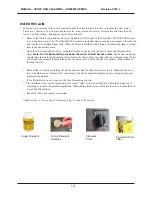
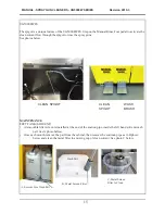
SOLVENT SELECTION
The adhesion quality of automotive paint has dramatically improved in recent years. The choice of
solvent is critical. Only use quality compliant solvent that is formulated for your paint and intended
for use with automatic spray guns cleaners. DO NOT USE CHLORINATED SOLVENT.
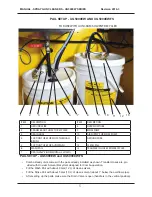
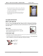
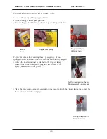
PAIL SETUP
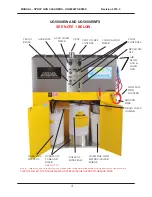
There are 3 pails to fill, 2 with solvent and 1 with tap water on the right. Open the drain valve which
controls the flow of solvent to the wash pail. See the photo, The Structure Figure 1 on page 4 and the
photos below.
Ring Terminal
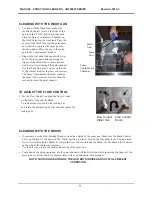
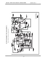
DRAIN VALVE - OPEN POSITION
(HANDLE IN VERTICAL POSITION).
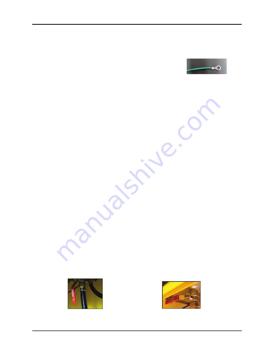
DRAIN VALVE I- CLOSED
(HANDLE IN HORIZONTAL POSITION).


