background image

MANUAL - SPRAY GUN CLEANERS - UG7500 SERIES  

REVISION 2011-05

12

TROUBLESHOOTING PROCEDURES

PROCEDURE 1

Blocked Fluid Passage In Diaphagm Pump

If the pump sounds like it is working but liquid does not flow, clear 

the 

fluid passage as follows: 

• 

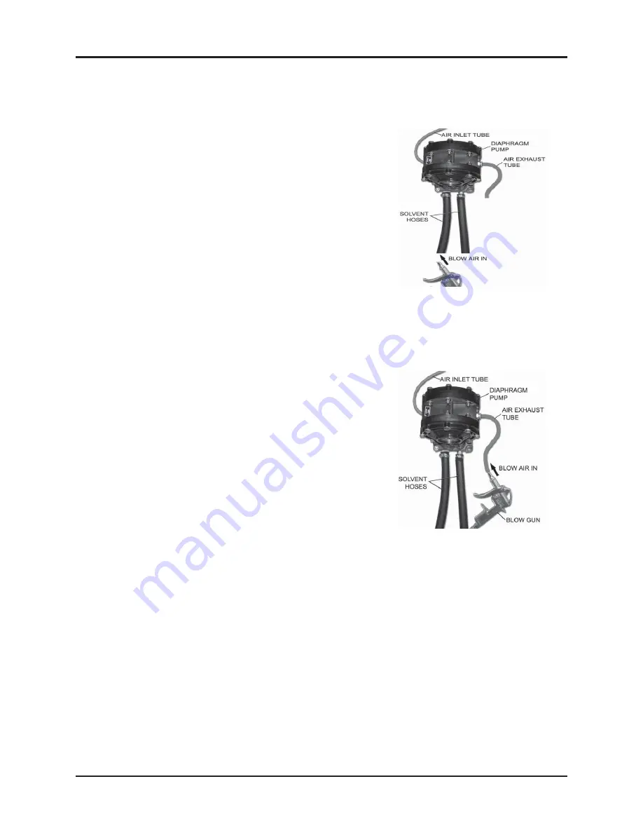
Remove suction tube from the pail and blow air at 85 PSI into 

the 

INLET Sovent Hose (see diagram). Step on foot pedal. This 
procedure may have to be repeated several times. If this pro-
cedure does not help, blow some water into the suction hose 
using a spray gun, wait one minute and step on foot pedal. 
This procedure may have to be repeated several times. If this 
procedure does not work, the pump must be replaced. 

If you need to replace the pump call your local dealer. The warran-

ty 

on the diaphragm pump is two years from date of purchase.


This procedure will also clear a blockage in the fluid line for the wash gun.  

PROCEDURE 2

Blocked Air Passage In Diaphragm Pump

If there is a steady hissing sound and the pump is not cycling, the spool valve has stalled due to a 
blocked air passage. Follow the procedure below to clear the blockage.

•  Connect a blow gun to an 85 PSI source. Locate 

the 

blue hose that extends from the air exhaust port of the dia-
phragm pump. Use a blow gun to blow air into the open end 
of this hose. Turn timer. If the procedure is successful, 

the 

pump will start working. The procedure may have to be 
repeated several times. If this procedure does not work, 
replace the pump.

• 

Cause: Contaminants in the air supply (water, oil, solid parti-

cles 

etc)

• 

Preventative Action: If necessary, install an Airline (Moisture) 
Filter.

PROCEDURE 3

Blocked Passage in Air Line

The components in the air line are the diaphragm pump, air valve, foot pedal, 3-way ball valve and regu-
lator. See the Flow Diagram and the section: Replacement Parts. 

To troubleshoot a component:
1) Disconnect the air line to the component using the quick disconnect. 
2) Step on foot pedal and check for presence of positive air pressure in the air line. If there is ample 
positive air pressure, replace the component.

If air pressure is absent, there is a faulty component upstream. Reconnect the air line and check the 
operation of the next component upstream by following steps 1 and 2 above.

Summary of Contents for UG7500 Series

Page 1: ...AY GUN CLEANERS UG7500 SERIES PATENTS U S A 4 785 836 CANADA 1293909 U S A 5 213 117 ENGLAND EP 0300248 UK EUROPE 0300248 ITALY 69760 BE 92 SWEDEN 0300248 GERMANY DE 38 75 412 FRANCE 8110528 0 JAPAN 1...

Page 2: ...ALLATION 7 OPERATION PRE CLEAN 7 CLEANING SPRAY GUNS AND CUPS 7 8 USING THE MANUAL WASH and RINSE 8 SPRAY GUN TESTING 8 HOSE CLEANING FACTORY OPTION 8 AFTER CLEANING 8 CONNECTING TO A SOLVENT RECYCLER...

Page 3: ...readily available for the operator at all times If you have any questions about the operation of this machine call your distributor or a Uni Ram Service Engineer CAUTIONS AND WARNINGS Always disconne...

Page 4: ...l this pedal operates the Manual Rinse Spigot CLEAN RINSE except NG Model MANUAL RINSE SPIGOT on NG Model use left pedal MANUAL WASH BRUSH AUTOMATIC WASH TIMER except NG Model AIR VENT ON OFF HOOD DOO...

Page 5: ...Part No 110 430 and 110 430PPS Hood Door Support Part No 780 3723 Remove the protective covers on all the oulets If any items are missing contact your supplier LOCATION Position in a well ventilated...

Page 6: ...as shown Move the pails into the cabinet and re connect the Suction Pipe of the left pail to the Drain Valve GROUND WIRE INSTALLATION Three ground wires are provided to discharge static electricity To...

Page 7: ...vent that is formulated for your paint and intended for use with automatic spray guns cleaners SOLVENT PAIL SETUP Remove the door of the base cabinet Move the Drain Valve handle to the open vertical p...

Page 8: ...onto the low spray jets and cup holders Close the lid and turn the Auto Wash Timer knob clockwise to start cleaning The cleaning takes about 60seconds Push and hold the Air Rinse button for about 3 se...

Page 9: ...n the tank CONNECTING TO A SOLVENT RECYCLER On the back of the machine connect the Transfer Hoses to the Solvent In and Solvent Out con nectors DAILY MAINTENANCE FILTER PADS AND SCREEN Inspect the fil...

Page 10: ...imer Replace timer INSIDE WALL OF TANK IS COATED WITH PAINT EVEN THOUGH OPERATOR MAINTAINS TANK Solvent lacks cleaning strength Replace solvent with solvent that is formulated for type of paint used a...

Page 11: ...all with proper adapter Incompatible solvent Replace incompatible solvent with solvent formulated for the type of paint used and for Automatic Spray Gun Cleaners Low pressure in air supply Increase ai...

Page 12: ...due to a blocked air passage Follow the procedure below to clear the blockage Connect a blow gun to an 85 PSI source Locate the blue hose that extends from the air exhaust port of the dia phragm pump...

Page 13: ...13 MANUAL SPRAY GUN CLEANERS UG7500 SERIES REVISION 2011 05 FLOW DIAGRAM S Use the diagram s to trace the flow of compressed air and solvent see page 17 for the NG model...

Page 14: ...Valve Assembly 780 4300 Valve Only 115 400BF Wash Sink REPLACEMENT PARTS UG7500 SERIES see page 16 for the NG model 780 520 Vent Tube 36 110J Air Jet not shown Diaphragm Pump UDP4TA Adjustable Foot 11...

Page 15: ...15 MANUAL SPRAY GUN CLEANERS UG7500 SERIES REVISION 2011 05 144 390 Flow Through Brush KIT SRP Spigot Kit Wash Sink with Screen Only no Cleaning tank REPLACEMENT PARTS UG7500NG...

Page 16: ...MANUAL SPRAY GUN CLEANERS UG7500 SERIES REVISION 2011 05 16 FLOW DIAGRAM UG7500NG ONLY...

Page 17: ...35 4331 Model Part No Description Non NG 110 430 Nozzle Adapter Conventional Systems Only Non NG 110 430PPS Nozzle Adapter All models Push On Non NG 780 3530 Nozzle Adapter Disposable Cup Systems Only...

Page 18: ...for the return of your original pump Conditions of Warranty As Uni ram Corporation has no control over the working conditions or circumstances under which the purchaser stores handles or uses the prod...

Reviews: