13
Owner’s manual
EN
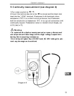
V. Continuity measurement (see diagram 6)
1)Turn rotary switch to
.
2) Insert the red test lead into the
terminal and the black test
lead into the “COM” terminal. If between both terminals show
resistance >70 , it is a short-circuit,no buzzer, but if between
both terminals show resistances 10 , it is a good connection with
continually buzzer. Resistance value on tested circuit display on
LCD (Unit is ).
Warning:
• To maintain the diodes measurement accuracy disconnect
circuit power and discharge all the high voltage capacitors
during the measuring resistance.
• Do not input higher than DC 60V and AC 30V voltage to pre
-
vent any damage and accident.
Diagram 6


