Owner’s manual
16
EN
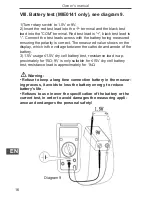
VIII. Battery test (MIE0141 onIy), see diagram 9.
1)Turn rotary switch to 1.5V or 9V.
2) Insert the red test lead into the terminal and the black test
lead into the “COM” terminal. Red test lead is “+”, black test lead is
“-”. Connect the test leads across with the battery being measured
ensuring the polarity is correct. The measured value shows on the
display, which is the voltage between the cathode and anode of the
battery.
3) 1.5V usage ≤1.5V dry cell battery test, resistance load is ap
-
proximately for 15Ω; 9V is only suitable for ≤15V dry cell battery
test, resistance load is approximately for 1kΩ.
Warning:
• Refuse to keep a long time connection battery in the measur
-
ing process, it avoids to loss the battery energy, to reduce
battery’s life.
• Refuses to use in over the specification of the battery or the
current test, in order to avoid damages the measuring appli
-
ance and endangers the personal safety!
Diagram 9


