UNI-T
UT139A/B/C OPERATING MANUAL
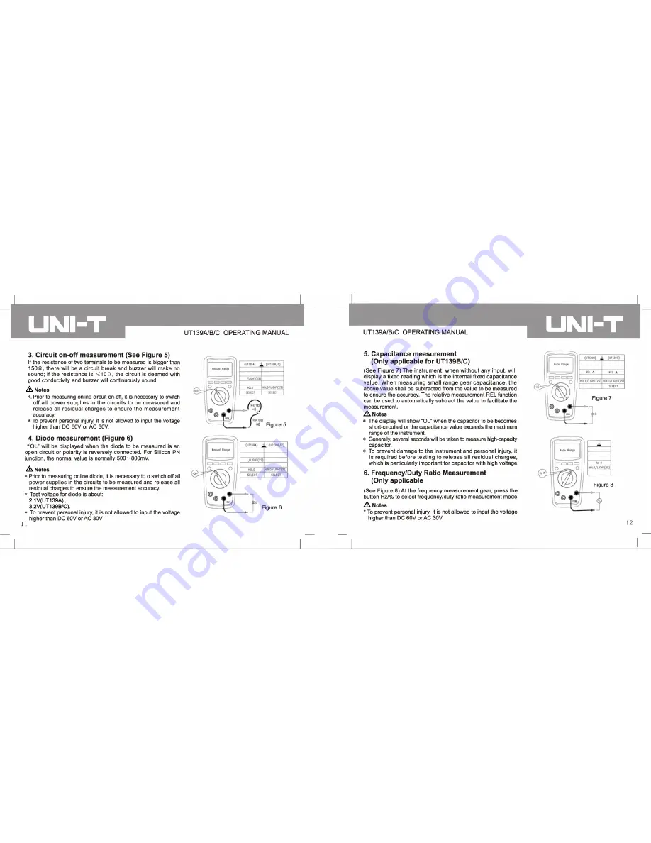
3. Circuit on-off measurement (See Figure 5)
If the resistance of two terminals to be measured is bigger than
1 5 0 ^ , there will be a circuit break and buzzer will make no
sound; if the resistance is ^ 1 0
Q,
the circuit is deemed with
good conductivity and buzzer will continuously sound.
^ Notes
*. Prior to measuring online circuit on-off, it is necessary to switch
off all power supplies in the circuits to be measured and
release all residual charges to ensure the measurement
accuracy.
* To prevent personal injury, it is not allowed to input the voltage
higher than DC 60V or AC 30V.
4. Diode measurement (Figure 6)
“ OL” will be displayed when the diode to be measured is an
open circuit or polarity is reversely connected. For Silicon PN
junction, the normal value is normally 500~800mV.
As.
Notes
* Prior to measuring online diode, it is necessary to o switch off all
power supplies in the circuits to be measured and release all
residual charges to ensure the measurement accuracy.
* Test voltage for diode is about:
2.1V(UT139A),
3.2V(UT139B/C).
* To prevent personal injury, it is not allowed to input the voltage
higher than DC 60V or AC 30V
11
UT139A/B/C OPERATING MANUAL
UNI-T
5. Capacitance measurement
(Only applicable for UT139B/C)
(See Figure 7) The instrument, when w ithout any input, will
display a fixed reading which is the internal fixed capacitance
value. When measuring small range gear capacitance, the
above value shall be subtracted from the value to be measured
to ensure the accuracy. The relative measurement REL function
can be used to automatically subtract the value to facilitate the
measurement.
^ Notes
* The display will show “OL” when the capacitor to be becomes
short-circuited or the capacitance value exceeds the maximum
range of the instrument.
* Generally, several seconds will be taken to measure high-capacity
capacitor.
* To prevent damage to the instrument and personal injury, it
is required before testing to release all residual charges,
which is particularly important for capacitor with high voltage.
6. Frequency/Duty Ratio Measurement
(Only applicable
(See Figure 8) At the frequency measurement gear, press the
button Hz/% to select frequency/duty ratio measurement mode.
^ Notes
* To prevent personal injury, it is not allowed to input the voltage
higher than DC 60V or AC 30V
Summary of Contents for TU13BA
Page 1: ...UT139A B C ...


