background image


UDP3305S Series Programmable DC Power Supply User Manual


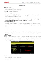
Delayer Parameter Setting 

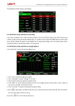
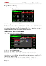
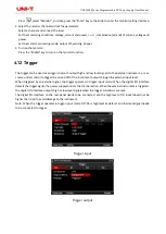
The interface of delayer is as follows: 


To set the delayer parameters manually: 

Press “Basic parameter” key to enter the setting interface. Users can edit the starting group number, the required 
number of output groups (maximum 2048 groups), the number of cycles (maximum 99999 times), and conditions 
for terminating the output state and stopping the delayer. Set parameters for each group: Set voltage, current, and 
time parameters for each group based on the required number of output groups. 

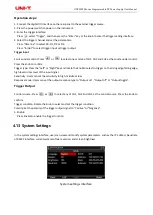
To set the list mode parameters using template: 

Press “Auto generation” to open the template editing menu. 


1. Press “Type” to select the desired template; 
2. Press “Start group” to edit the start group number; 
3. Press "Total points" to set the number of points required for this delay (maximum 2048 points); 
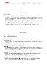
4. Press "Mode" or "Time” to set parameters for each template. Press "Mode" to select 01 code (off/on cycle) or 
10 code (on/off cycle). Press "Time” to edit time base value, step value, open time and close time, etc. (the menu       
varies according to different templates). 
5. After all parameters are set, press "Generate" to complete the delayer template output setting. 
6. Press "Enable", the delayer will control the automatic output of the corresponding channel. 
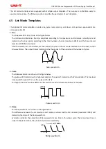
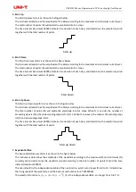
Templates 

Summary of Contents for UDP3305S Series

Page 1: ...UDP3305S Series Programmable DC Power Supply User Manual ...

Page 2: ... to any product specification and pricing changes Uni Trend Technology China Co Ltd all rights reserved Trend reserves all rights Information in this manual supersedes all previously published versions No part of this manual may be copied extracted or translated by any means without the prior permission of Uni Trend UNI T is the registered trademark of Uni Trend Technology China Co Ltd Warranty Se...

Page 3: ...s Limited Warranty and Liability The warranty is inapplicable to any defects failures or damages caused by accident normal wear of components use beyond specified scope or improper use of product or improper or insufficient maintenance UNI T is not obliged to provide the services below as prescribed by the warranty a Repair damage caused by installation repair or maintenance of personnel other tha...

Page 4: ...on layer of the test leads is damaged or whether the leads are exposed or conducting If the leads are damaged replace them Fuses Only fuses specified for this product are allowed Overvoltage protection Please ensure that no excessive voltage such as the voltage caused by lightning reaches the product to avoid electric shock Do not open the housing of the product Do not operate the product when the...

Page 5: ... CH2 33V CH3 6 2V CH4 5V CH1 5 2A CH2 5 2A CH3 3 2A CH4 2A UDP3305S E UDP3305S series is a high performance programmable DC power supply with a clear interface excellent performance indexes multiple analysis functions and communication interfaces which can meet diverse testing requirements 1 1 1 Features The maximum power can reach 373W and the output of each channel is individually controllable T...

Page 6: ...urrent and power values which is convenient for users to know the output status and trend of the instrument The instrument can automatically control the fan speed according to the operating conditions to reduce the noise Fan fault detection and alarm function 10 sets of settings to save and recall supports U disk read and storage Five digit voltage four digit current high precision display resolut...

Page 7: ...2mV Load regulation 0 01 2mV Series connection Power supply regulation 0 01 3mV Power supply regulation 0 01 3mV Load regulation 300mV Load regulation 300mV Tracking error 0 5 10mV 10 30V no load 0 5 30mV 0 9 99V no load Connected load 300mV 0 5 10mV 10 30V no load 0 5 30mV 0 9 99V no load Connected load 300mV Measurement Display Voltage full scale 4 digits display LCD Voltage full scale 5 digits ...

Page 8: ...l load 45ms no load 400ms Fall full load 45ms no load 400ms CH3 Rise full load 15ms no load 13ms Rise full load 15ms no load 13ms Fall full load 22ms no load 100ms Fall full load 22ms no load 100ms Temperature coefficient per CH1 Voltage 0 01 5mV Current 0 01 2mA Voltage 0 01 5mV Current 0 01 2mA CH2 Voltage 0 01 5mV Current 0 01 2mA Voltage 0 01 5mV Current 0 01 2mA CH3 Voltage 0 01 2mV Current 0...

Page 9: ...UDP3305S Series Programmable DC Power Supply User Manual 3 12 Front Panel 1 2 1 Keys Key Function WAVE Enable the waveform display function ...

Page 10: ...ct channel 3 and switch between 1 8V 2 5V 3 3V 5V ON OFF Enable or disable the output of the corresponding channel ALL ON OFF Enable or disable the outputs of all the channels Knob Select or edit the parameter press it to confirm Step through parameters towards the left Step through parameters towards the right LOCK Push to lock long push to unlock PRESET Preset parameters of channels series paral...

Page 11: ...uct is damaged scratched or has other defects 2 Check whether the instrument accessories are missing according to the packing list If it is damaged or the accessories are missing please contact Uni Trend Instrument Sales Department or the distributor immediately Accessories Quantity Remarks Programmable DC power supply 1 The model is subject to the actual order 3C power cord 1 250V 4A spare fuse 1...

Page 12: ... When replacing the fuse please remove the external power cord first then open the fuse slot under the power interface take out the old fuse and replace it with a new one and install the fuse slot back after completion Warning Please do not use the damaged power cord 3 13 Operating Environment UDP3305S series can only be used in normal temperature and low condensing zone The general environment re...

Page 13: ...o the AC power input terminal and the three hole AC power output terminal on the rear panel AC power supply with grounding wire Warning The three hole power cord that comes with the instrument has an independent grounding terminal The power supply used must be three hole and grounded otherwise it may cause electric shock Press the power switch to power on the instrument 3 2 Output Terminals 1 Each...

Page 14: ...Voltage Output Constant Current Output Power Supply Series and Parallel Connections List Mode and Delayer Advanced Functions Display Setting Store and Recall System Settings 4 1 Constant Voltage Output UDP3305S series power supply provides two output modes constant voltage output CV and constant current output CC In CV mode the output voltage equals the voltage setting value and the output current...

Page 15: ... channel 4 As shown in the figure below connect the load with the channel output terminals of the corresponding channel at the front panel Caution Pay attention to the polarity when connecting them to avoid damaging the instrument and the devices connected to the instrument 5 Set the voltage and current Method 1 Press the Voltage or Current key and the cursor will be displayed at the end of the vo...

Page 16: ...e as setting voltage in constant voltage mode 5 Set the current It is the same as setting current in constant voltage mode 6 Set overvoltage and overcurrent protection It is the same as setting overvoltage and overcurrent protection in constant voltage mode 7 Turn on the output Turn on the output of the corresponding channel and the actual output voltage output current output power as well as the ...

Page 17: ...s are connected in series VL V1 V2 When two insulated channels are connected in parallel IL I1 I2 Power Supply Series Connection Higher voltages can be provided by connecting power supplies in series In this case the output voltage is the sum of the output voltages of all the channels When the UDP3305S series power supply enters the series mode users only need to set its output voltage output curr...

Page 18: ...ode At this time the CH1 and CH2 output indicators are all green CV mode If the indicator is red please check whether the set current meets the load requirements Power Supply Parallel Connection High currents can be provided by connecting power supplies in parallel In this case the output current is the sum of the output currents of all the channels When the UDP3305S series power supply enters the...

Page 19: ...l memory of the system 10 groups can be stored each and users can define the file name Users can also store list mode parameters list mode file with the suffix LST and delayer parameters delay file with the suffix DLY in external memory The number of external storage files is not limited by the system only limited by the size of the external storage space Operation steps 1 Press the power switch t...

Page 20: ... on the required number of output groups To set the list mode parameters using template Press Template to open the template editing menu 1 Press Type to select the desired template 2 Press Edit object to select Voltage or Current 3 Define waveform start group values and total points 4 Press More to set the waveform parameters such as the voltage maximum and minimum current high and low levels puls...

Page 21: ...f output groups To set the list mode parameters using template Press Auto generation to open the template editing menu 1 Press Type to select the desired template 2 Press Start group to edit the start group number 3 Press Total points to set the number of points required for this delay maximum 2048 points 4 Press Mode or Time to set parameters for each template Press Mode to select 01 code off on ...

Page 22: ...constructed set the number of cycles in the list mode interface to continuously output Sine waveforms The output time is determined by the product of the period and the number of cycles Sine waveform 2 Pulse The Pulse waveform is as shown in the figure below The pulse width t determines the high level duration The period T determines the Pulse duration The low level time equals the period T minus ...

Page 23: ...e figure below The instrument determines the amplitude of the Ramp according to the maximum and minimum currently set The total number of points N will divide the amplitude into N 1 steps When N is an odd the number of ascending steps is N 1 2 and descending steps is N 1 2 1 When N is an even the number of ascending steps is N 2 and descending steps is N 2 The time interval maximum 99999 indicates...

Page 24: ... a template that controls the On Off state of the output terminal 0 means off and 1 means on 0 1 Pattern the state is set to Off and On alternately 1 0 Pattern the state is set to On and Off alternately 2 Fix Time Fix time mode is a template for setting the output terminal on time Max 99999s and off time Max 99999s Users set the output on delay time the duration when the output status is On and th...

Page 25: ...le respectively and also supports external storage Press to enter the state storage interface The storage contents include the present setting values of voltage and current of each channel overvoltage and overcurrent values the setting values of triggers and monitors upper computer connection baud rate and IP address etc State file storage interface the file suffix is STA After entering the list m...

Page 26: ...he parameter group file to be recalled After pressing the Read key the screen displays Load succeeded Press the ESC key twice to return to the initial interface of list mode delayer Press the Enable key to read the stored files File read interface 4 9 Waveform Display UDP3305S series power supply has waveform display function which can display the output voltage current and power of each channel o...

Page 27: ...ant Voltage Output Constant Current Output Power Supply Series and Parallel Connections set the voltage current over voltage and over current protection values For list mode and delayer waveforms refer to chapter List Mode Timer and Delayer 4 View the waveform Turn on the selected output channel to view the waveform To view the list mode and delayer waveforms press again 4 10 Preset UDP3305S serie...

Page 28: ...e interface automatically jumps back to the power on interface and the parameters of each channel are displayed as the preset parameter values 4 11 Monitor The monitor monitors the voltage current and power of each independent channel series and parallel channel and gives alarm to the output of each channel and determines whether to close the output according to the set conditions Operating mechan...

Page 29: ...the external instrument or as a source under control to trigger the on and off of the instrument output through the external input level When triggered by an external signal the trigger operates in trigger input mode When the digital I O interface detects the trigger signal the power supply controls the channel action When the external instrument is triggered the digital I O interface outputs high...

Page 30: ...e Left or Right key and rotate the knob to select to trigger on the rising edge falling edge high level or low level of the input signal Sensitivity Users can set the sensitivity to high middle or low Response mode Users can set the output response type to Output on Output off or Output toggle Trigger Output Control source Press or to select any of CH1 CH2 and CH3 as the control source Press the k...

Page 31: ...UDP3305S Series Programmable DC Power Supply User Manual System software version ...

Reviews: