Quick Guide
UPO1000 Series
13/17
6.
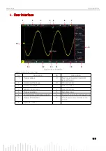
User Interface
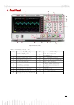
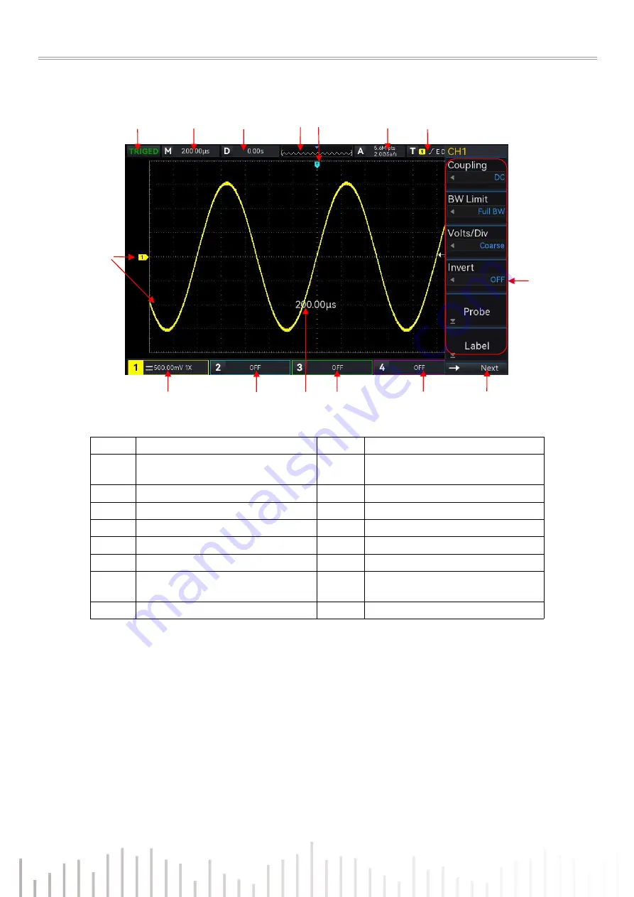
Figure 5 User Interface
Table 3 Icon of User Interface
No.
Description
No.
Description
1
Trigger status
9
Next page /System time/USB
icon/LAN icon
2
Horizontal time base
10
CH4 state label
3
Horizontal offset
11
CH3 state label
4
Waveform indicator
12
CH2 state label
5
Trigger position
13
CH1 state label
6
Sampling rate
and Storage depth
14
Analog channel label and waveform
7
Trigger information
15
Time base scale, volts/div scale
popup
8
Operation menu
1
2
3
4
6
7
5
8
9
13
14
12
11
10
15


