23
/
99
e. Trigger mode
:
Auto, normal and single.
f.
Trigger level: Display the current trigger level, it corresponding to the right side of screen
.
Adjusting trigger control LEVEL knob in front of panel to change the parameter.
⑥
CH1 vertical scale identification
:
Display CH1 activation state, channel coupling, bandwidth limit,
vertical scale and probe attenuation coefficient.
a. Channel activation state
:
b. Bandwidth limitation: When the bandwidth limit function is turned on, an icon
will appear in the
display
c.
Vertical scale: Display the vertical scale of CH1. When CH1 is activated, the vertical scale can
be adjusted with the vertical scale knob in front of panel.
d. Probe attenuation coefficient: Display CH1 probe attenuation coefficient 0.001×
,
0.01×
,
0.1×
,
1×
,
10×
,
100×
,
1000× and user-defined.
⑦
USB host identification
:
USB icon will be shown when USB device is connected.
⑧
LAN identification
:
LAN icon will be shown when network wire is connected.
⑨
The current date and time.
⑩
Soft key menu
:
Display the operation menu, press the corresponding knob to select menu. Press
F1 ~ F5 to change the sub-menu.
⑪
Analog channel identification and Waveform
:
Display channel identification and waveform of
CH1~CH2, the color of channel identification will be the same with waveform.
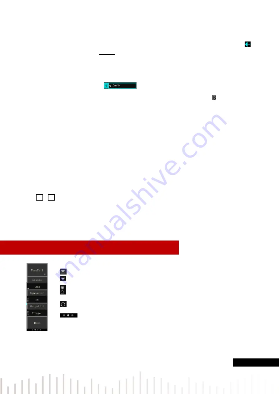
4.7 Introduction of Special Symbol
Take the left menu as example
This symbol presents there has the next menu
This symbol presents there has pull-down menu
This symbol presents there are two option
This symbol presents it can be adjusted by multipurpose knob
Circle number presents the page of menu, single page has no small circle, and
two or more pages will have small circle display. Press F5 to turn pages.


