40
/
99
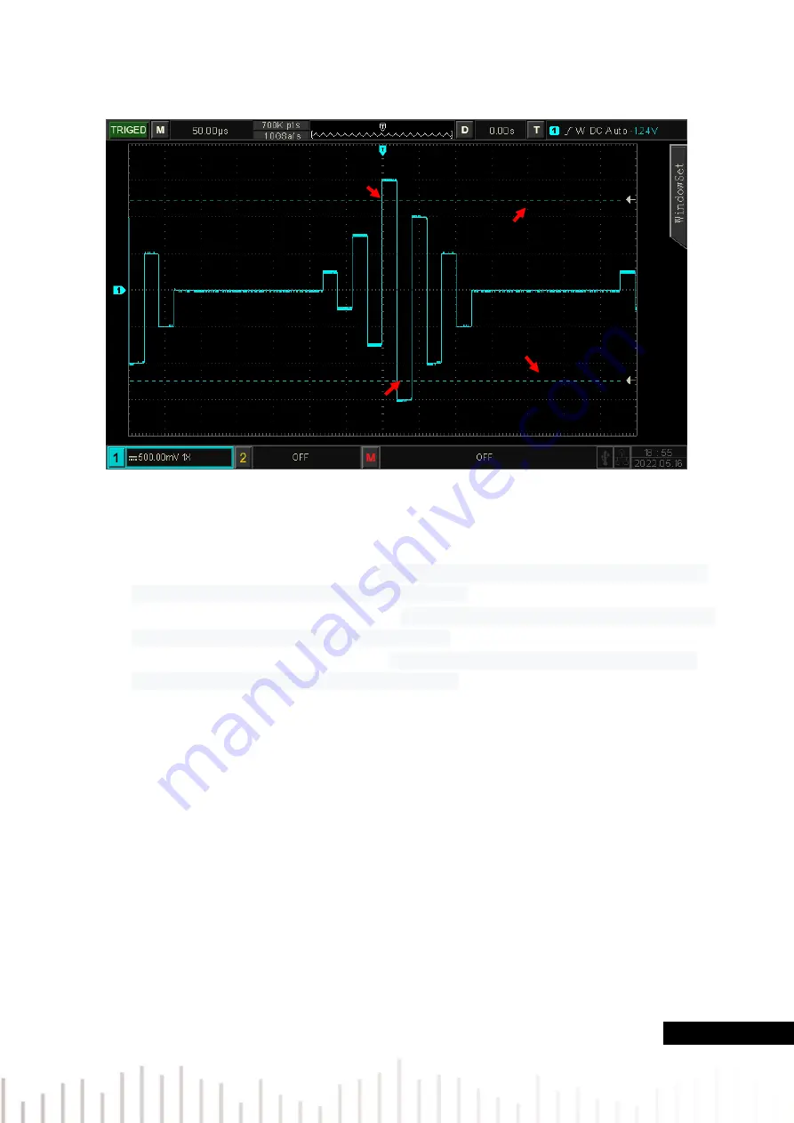
Figure 7-4
(1) Slope
Select which edge that the input signal can be triggered. It can select rising edge, falling edge or
random edge. The current slope is displayed in the upper right corner of the screen.
a. Rising edge
:
It will be generated when
the trigger on the rising edge of the input signal and
the voltage level is higher than the setting high level.
b. Falling edge
:
It will be generated when the
trigger on the falling edge of the input signal and
the voltage level is lower than the setting low level.
c.
Random edge
:
It will be generated when
the trigger on the rising/falling edge of the input
signal and the voltage level is within the setting level
.
(2) Trigger Position
Trigger position can set enter, exit and time. Select trigger position to confirm the timing of trigger.
a. Enter
:
It will be generated when the input signal enter the specified trigger level.
b. Exit
:
It will be generated when the input signal exit the specified trigger level.
c.
Time
:
It will be generated when the over-amplitude entered, accumulated hold time is greater
than or equal to the preset over-amplitude time
(3) Setting
When trigger position is set to “Time”, the setting time takes effect and is triggered when condition
is met. The range can be set to8ns ~ 10s.
rising
edge
falling edge
Trigger level-high level
Trigger level-low level
平


