background image

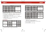
10) AC Current

Frequency response

40Hz~1kHz

1kHz~10kHz

40Hz~1kHz

1kHz~10kHz

40Hz~1kHz

1kHz~10kHz

40Hz~1kHz

1kHz~10kHz

40Hz~1kHz

1kHz~10kHz

Accuracy

± (0.8%+10)

± (3%+50)

± (0.8%+10)

± (3%+50)

± (1.2%+10)

± (3%+50)

± (1.2%+10)

± (3%+50)

± (1.2%+10)

± (3%+50)

Resolution

0.01μA

0.1μA

1μA

10μA

1mA

Range

220μA

2200μA

22mA

220mA

20A

UT161E

Range

UT161B/UT161D

600.0μA

6000μA

60.00mA

600.0mA

6.000A

10.00A (UT161B)

20.00A (UT161D)

Resolution

0.1μA

1μA

10μA

0.1mA

1mA

10mA

10mA

Accuracy

± (1.2%+5)

± (1.5%+5)

± (2.0%+5)


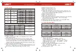
Display: True RMS


Frequency response: 40Hz~500Hz (UT161B), 40Hz~1kHz (UT161D), 


40Hz~10kHz (UT161E)


Accuracy guarantee (UT161B/UT161D): 5%~100% of 600.0μA range, 


1%~100% of other ranges; open circuit allows least significant digit 

5


Accuracy guarantee (UT161E): 1%~100% of range at 40Hz~1kHz, 10%~100% 


of range at 1kHz~10kHz (the minimum measured current at μA ranges is 30μA); 


open circuit allows least significant digit 

10


The AC crest factor can be 

3.0 at 3000 counts, and can only be 

1.5 at 


6000 counts. The additional error should be added according to the crest 


factor of a non-sinusoidal wave as follows (UT161B/UT161D): 

a) Add 4% when crest factor is 1~2
b) Add 5% when crest factor is 2~2.5
c) Add 7% when crest factor is 2.5~3
    The AC crest factor can be 

2.0 at 10000 counts, and can only be 

1 at 

    22000 counts. The additional error should be added according to the crest 
    factor of a non-sinusoidal wave as follows (UT161E): 
a) Add 4% when crest factor is 1~2
b) Add 5% when crest factor is 2~2.5
c) Add 7% when crest factor is 2.5~3
    Frequency measurement range: 40Hz~500Hz (UT161B), 40Hz~1kHz (UT161D), 
    40Hz~10kHz (UT161E); input amplitude: 

50% of current range.

    Duty ratio is for reference only. 
    Frequency accuracy: ± (0.1%+4); resolution: 0.1Hz (UT161B/UT161D) 
    Overload protection: Same as that for DC current

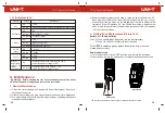
11)  Frequency/Duty Ratio

Range

10Hz~220MHZ

0.1%~99.9%

Resolution

0.01Hz~0.01MHz

0.1%

Accuracy

± (0.01%+5)

± (2%+5)

UT161E

Range

10.00Hz~10.00MHZ

0.1%~99.9%

Resolution

0.01Hz~0.01MHz

0.1%

Accuracy

± (0.1%+4)

± (2%+5)


Frequency input amplitude: 

  ≤

100kHz: 200mVrms 

≤ 

input amplitude 

≤ 

20Vrms                 


>100kHz~1MHz: 600mVrms 

≤ 

input amplitude 

≤ 

20Vrms


>1MHz (UT161B/UT161D): 1Vrms 

≤ 

input amplitude 

≤ 

20Vrms


>1MHz~40MHz (UT161E): 1Vrms 

≤ 

input amplitude 

≤ 

20Vrms


>40MHz (UT161E): Not specified


Duty ratio measurement is only applicable to square waves.


1Vpp 

≤ 

input amplitude 

≤ 

20Vpp


Frequency 

10kHz, duty ratio: 10.0% ~ 90.0%


Overload protection: 1000V

UT161B/UT161D

33

34

Summary of Contents for UT161 Series

Page 1: ...P N 110401109612X 1000V True RMS Digital Multimeter User Manual UT161 Series ...

Page 2: ...ni Trend guarantees that the product is free from any defect in material and workmanship within one year from the purchase date This warranty does not apply to damage caused by accident negligence misuse modification contamination or mishandling The dealer shall not be entitled to give any other warranty on behalf of Uni Trend If you need warranty service within the warranty period please contact ...

Page 3: ...al temperature alarm low battery indication backlight auto power off and NCV functions the meter is an ideal measuring tool for many application fields Open the package box and take out the meter Please double check whether the following items are missing or damaged 1 User manual 1 pc 2 Test leads 1 pair 3 Adapter socket UT161D UT161E 1 pc 4 K type thermocouple UT161D 1 pc 5 USB cable 1 pc 6 Downl...

Page 4: ... earth ground 8 Place the function dial in the correct position before measurement 9 Before measuring resistance diode continuity or capacitance switch off the power supply of the circuit and fully discharge all capacitors 10 Before measuring current make sure the fuses are intact 11 Do not use or store the meter in high temperature high humidity flammable explosive or strong magnetic field enviro...

Page 5: ...ode test Continuity test Relative value measurement Resistance units ohm kilohm megaohm Voltage units millivolt volt Current units microampere milliampere ampere Capacitance units nanofarad microfarad millifarad Frequency duty ratio Data transmission Transistor magnification UT161E Non contact voltage detection Peak measurement UT161D UT161E Maximum Minimum measurement Celsius Fahrenheit UT161D Lo...

Page 6: ...urement Frequency and duty ratio measurement Non contact voltage detection Short press Press a button for less than 2s Long press Press a button for more than 2s 1 Button Short press to switch between functions in each compound function position 2 Button Short press to enter the manual range mode and change the range Long press to exit the manual range mode 3 Button Short press to switch between f...

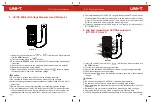
Page 7: ...er test 2 DC Voltage Measurement Picture 5 DC Voltage Measurement 1 Insert the red test lead into the or terminal and black test lead into the COM terminal 2 Turn the function dial to the or position 3 Short press the button to switch to DC voltage measurement if SELECT required 4 Connect the test leads with the measured load or power supply in parallel 5 Read the voltage value on the display if t...

Page 8: ...t is below 10kΩ the error can be ignored 0 1 4 LoZ low impedance ACV Measurement UT161D Picture 7 1 Insert the red test lead into the or terminal and black test lead into COM terminal the 2 Turn the function dial to the position 3 Connect the test leads with the measured load or power supply in parallel 4 Read the voltage value on the display 5 Short press the button to display the frequency duty ...

Page 9: ...t and use the relative value measurement REL mode leads If the resistance is not less than 0 5Ω when the test leads are short circuited please check if the test leads are loose or abnormal When measuring high resistance it is normal to take a few seconds to stabilize the reading 6 Continuity Test Picture 9 1 Insert the red test lead into the or terminal and black test lead into the COM terminal 2 ...

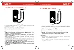
Page 10: ...e power supply of the circuit and fully discharge all capacitors 8 Capacitance Measurement Picture 11 1 Insert the red test lead into the or terminal and black test lead into the COM terminal 2 Turn the function dial to the or position 3 Short press the button to switch to capacitance measurement SELECT 4 Touch the probes to the capacitor pins 5 Read the capacitance value on the display after it g...

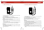
Page 11: ...tion of the measured transistor 10 Frequency Duty Ratio Measurement Picture 13 1 Insert the red test lead into the or terminal and black test lead into the COM terminal 2 Turn the function dial to the position 3 Short press the button to switch to frequency duty ratio measurement required if 4 Read the frequency duty ratio value on the display Caution Use caution when working with voltages above A...

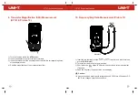
Page 12: ...5 Read the current value on the display if the current is 10A the red indicator light will be on and the buzzer will sound an alarm 6 When measuring AC current short press the button to display the frequency duty ratio of the measured current Caution To prevent possible electric shock fire or personal injury switch off the power supply of the circuit and then connect the meter with the circuit in ...

Page 13: ... USB communication module into the USB access port of the meter and the LCD will display Picture 17b 3 If USB data transmission is not needed during measurement long press the button or pull out the USB module to disable data transmission and will disappear 4 To recover this function long press the button or insert the USB module 5 The USB communication software can be downloaded from the official...

Page 14: ... III 1000V CAT IV 600V 19 Certification CE ETL 20 Pollution degree 2 21 Information of usage Indoor and outdoor 2 Electrical Specifications Accuracy a of reading b digits 1 year warranty Ambient temperature 23 C 5 C 73 4 F 9 F Relative humidity 75 Caution To ensure measurement accuracy the operating temperature should be within 18 C 28 C and the fluctuation range should be within 1 C When the temp...

Page 15: ... counts and can only be 1 at 22000 counts The additional error should be added according to the crest factor of a non sinusoidal wave as follows UT161E a Add 4 when crest factor is 1 2 b Add 5 when crest factor is 2 2 5 c Add 7 when crest factor is 2 5 3 Frequency measurement range 40Hz 500Hz UT161B 40Hz 1kHz UT161D 40Hz 10kHz UT161E input amplitude 10 of voltage range Duty ratio is for reference ...

Page 16: ...ell connected circuit Resistance 50Ω audio visual alarm Open circuit voltage About 3V For normal diodes the buzzer will beep once For short circuit the buzzer will beep for a long time Resolution 0 1Ω 0 001V Range Overload protection 1000V When the forward voltage drop is within 0 12V 2V the buzzer will beep once When the forward voltage drop is 0 12V the buzzer will beep for a long time 6 Transis...

Page 17: ...s 8 Temperature Range 40 0 C 0 300 C 300 1000 C 40 32 F 32 572 F 572 1832 F 40 1000 C 40 1832 F Accuracy 1 0 3 C 1 0 2 C 1 0 3 C 1 0 6 F 1 0 4 F 1 0 6 F Resolution 0 1 C 1 C 0 2 F 2 F The measured temperature should be less than 230 C 446 F 9 DC Current UT161E Accuracy Range 220 00μA 2200 0μA 22 000mA 220 00mA 20 000A Resolution 0 01μA 0 1μA 1μA 10μA 1mA 0 5 10 1 2 50 UT161B UT161D Accuracy Range ...

Page 18: ...a Add 4 when crest factor is 1 2 b Add 5 when crest factor is 2 2 5 c Add 7 when crest factor is 2 5 3 The AC crest factor can be 2 0 at 10000 counts and can only be 1 at 22000 counts The additional error should be added according to the crest factor of a non sinusoidal wave as follows UT161E a Add 4 when crest factor is 1 2 b Add 5 when crest factor is 2 2 5 c Add 7 when crest factor is 2 5 3 Fre...

Page 19: ...20MΩ mAµA 35 36 1 Clean the meter casing with a damp cloth and mild detergent Do not use abrasives or solvents 2 If there is any malfunction stop using the meter and send it for maintenance 3 The maintenance and service must be implemented by qualified professionals or designated departments 4 Resistance measurement can be used to check the built in 600mA and 11A fuses Operation Picture 18a Insert...

Reviews: