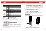
Please check the internal batteries first. If “ ” is displayed, replace the batteries
in time. Please also pay attention to the warning sign “ ” beside the input
terminals, which indicates that the measured voltage or current must not exceed
the values marked on the meter.
1) Insert the red test lead into the or terminal, and black test lead
into the
COM
terminal.
2) Turn the function dial to the , , or position.
3) Short press the
SELECT
button to switch to AC voltage measurement or LPF
ACV measurement (UT161E, manual maximum range by default) if required.
4) Connect the test leads with the measured load or power supply in parallel.
5) Read the voltage value on the display (if the voltage is >1000V, the red indicator
light will be on and the buzzer will sound an alarm).
6) Short press the button to display the frequency/duty ratio of the measured
voltage.
Caution:
Do not input a voltage over 1000V or it may damage the meter.
Be cautious to avoid electric shock when measuring high voltages.
After completing the measurement, disconnect the test leads from the circuit
under test.
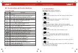
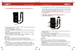
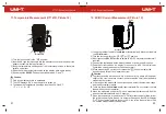
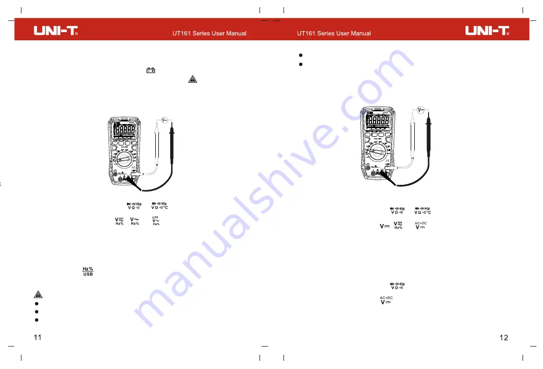
2. DC Voltage Measurement (Picture 5)
DC Voltage Measurement
1) Insert the red test lead into the or terminal, and black test lead
into the
COM
terminal.
2) Turn the function dial to the , , or position.
3) Short press the
button to switch to DC voltage measurement if
SELECT
required.
4) Connect the test leads with the measured load or power supply in parallel.
5) Read the voltage value on the display (if the voltage is >1000V, the red indicator
light will be on and the buzzer will sound an alarm).
AC+DC Voltage Measurement (UT161E)
1) Insert the red test lead into the terminal, and black test lead
into the
COM
terminal.
2) Turn the function dial to the position.
3) Short press the
button to switch to AC+DC voltage measurement.
SELECT
4) Connect the test leads with the measured load or power supply in parallel.
5) Read the voltage values on the display. The AC and DC voltages are displayed
alternately.
VIII. Operating Instructions
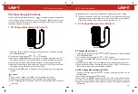
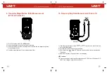
1. AC Voltage Measurement (Picture 4)
Before each use, verify meter operation by measuring a known voltage.
The input impedance of the meter is about 10M
Ω
. This load effect may cause
measurement errors in high-impedance circuits. In most cases, if the impedance
of the circuit is below 10k
Ω
, the error can be ignored (
≤
0.1%).
Picture 4
Picture 5


