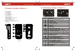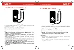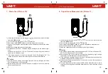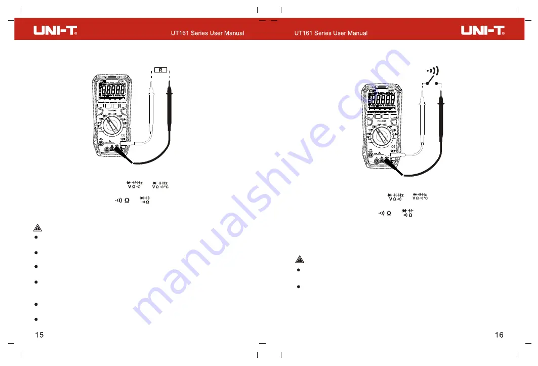
5. Resistance Measurement (Picture 8)
1) Insert the red test lead into the or terminal, and black test lead
into the
COM
terminal.
2) Turn the function dial to the or position.
3) Touch the probes to the test points in the circuit.
4) Read the resistance value on the display.
Caution:
Use caution when working with voltages above AC 30Vrms, 42Vpeak or DC
60V. Such voltages pose a shock hazard.
If the measured resistor is open or the resistance exceeds the maximum range,
the LCD will display “OL”.
Before measuring resistance, switch off the power supply of the circuit, and
fully discharge all capacitors.
When measuring low resistance, the test leads will produce 0.1Ω~0.3Ω
measurement error. To obtain accurate measurement, short-circuit the test
and use the relative value measurement (REL) mode.
leads
If the resistance is not less than 0.5Ω when the test leads are short-circuited,
please check if the test leads are loose or abnormal.
When measuring high resistance, it is normal to take a few seconds to stabilize
the reading.
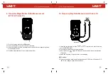
6. Continuity Test (Picture 9)
1) Insert the red test lead into the or terminal, and black test lead
into the COM terminal.
2) Turn the function dial to the or position.
3) Short press the
button to switch to continuity test.
SELECT
4) Touch the probes to the test points in the circuit.
5) Measured resistance <50Ω: The circuit is in good conduction status; the
buzzer beeps continuously and the green indicator light is on.
Caution:
Use caution when working with voltages above AC 30Vrms, 42Vpeak or DC
60V. Such voltages pose a shock hazard.
Before testing continuity, switch off the power supply of the circuit, and fully
discharge all capacitors.
Picture 8
Picture 9


