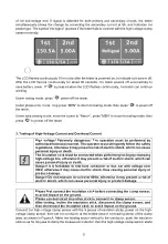
of the low-voltage end. If signal is detected for both primary and secondary circuits, the tester
simultaneously shows the change by converting the secondary current at 5A, and indicates the
phase type. The symbol “No signal” appears if the tester fails to connect with the high-voltage clamp
sensor normally.
The LCD flashes continuously 10 minutes after the tester is powered on, to indicate auto power off.
After the LCD flashes continuously for about 30 seconds, the tester powers off automatically to
save battery power. If “
” is pressed when the LCD flashes continuously, the tester can continue
working.
Under testing mode, press “
” power off the tester.
Under phase error mode, long press “MEN” to return to testing mode, then press “
” to power off
the tester.
Under data viewing mode, move the cursor to “Return”, press “MEN” to return to testing mode, then
press “
” to power off the tester.
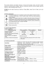
3. Testing of High-Voltage Current and Overhead Current
High voltage! Extremely dangerous! The operation must be performed by
authorized trained personnel. The operator must stringently follow the safety
regulations, otherwise it may present a risk of electric shock, which can cause
personal injury or death.
The insulation stick must be connected when performing testing by clamping
high-voltage line, otherwise it may present a risk of electric shock, which can
cause personal injury or death.
Danger! It is forbidden to test bare conductor or bus bar with voltage over
35kV, otherwise it may cause electric shock, thus causing personal injury or
product damage.
Danger! Do not measure circuit over 800A, otherwise it may present a risk of
electric shock, which can cause personal injury or product damage.
Please first connect the insulation stick before connecting the clamp sensor,
to avoid impact on the ground.
Please use dedicated insulation stick to connect the clamp sensor.
After testing, incline the insulation stick, disconnect the clamp sensor, and
then disconnect the insulation stick, to avoid impact on the ground.
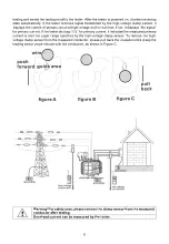
Connect the high-voltage clamp sensor with the 5 pieces of insulation sticks, power on the high-
voltage clamp sensor, then set the conductor at the middle area of the leading sector of the clamp
jaws, as shown in Figure A. Make the leading sector vertical to the conductor, push the insulation
stick so as for the jaws to clamp the measured conductor, then the high-voltage clamp sensor starts
5


