10
Danger! Do not measure voltage line over 600V, otherwise it can
pose a risk of electric shock, which may cause personal injury or
equipment damage.
Danger! Do not measure any line over 1000A, otherwise it may
cause equipment damage.
Please perform wiring strictly according to the user manual. Do
not connect I1, I2 and I3 inversely.
Please remove the test leads from measured line before
disconnecting the test leads with the voltammeter.
The phase relations of the voltammeter is: U1U2, U2U3, U3U1, I1I2,
I2I3, I3I1, U1I1, U2I2 and U3I3, the previous signals exceed the next
ones for all the phases.
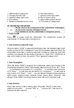
The U1, U2 and U3 terminals and the right arrows at the
corresponding current clamps are the same-polarity ends.
For phase testing, the direction of current flowing into the clamp
shall be consistent with the direction of arrow at the clamp.
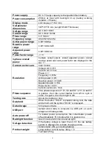
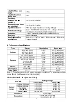
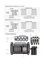
The voltammeter measure 3-phase AC voltage and current, phase between
voltages, phase between currents, phase between voltage and current, frequency,
active power, reactive power, apparent power, power factor, 3-phase current
vector sum, and identify phase sequence, inductive and capacitive circuits, etc.
Wiring of tests:
Single-phase testing:
Connect the measured voltage lines L and N with U1
YELLOW and COM BLACK terminals correspondingly, then the current clamp I1
clamps the measured line L. “U2 GREEN, COM BLACK and I2” or “U3 RED, COM
BLACK and I3” can also be connected.
3-phase 4-wire testing:
Connect the measured voltage lines UA YELLOW, UB
GREEN, UC RED and N BLACK with U1 YELLOW, U2 GREEN, U3 RED and
COM BLACK terminals correspondingly, then the current clamps I1, I2 and I3
clamp the measured lines IA, IB and IC correspondingly.
3-phase 3-wire testing:
Connect the measured voltage lines UA YELLOW, UC
RED and UB GREEN with U1 YELLOW, U3 RED and COM BLACK terminals,
then the current clamps I1 and I3 clamp the measured lines IA and IC
correspondingly. See “Reference wiring diagrams”.
Inductive and capacitive loads, phase sequence and polarity can be identified
according to the phase relations. If the phase of U1I1 is between 0.0 and 90.0,
then the measured load is inductive; if between 270.0 and 360.0, then capacitive.
If the phase is approximate to 120.0, then the phase sequence is positive and the
polarity is same; if approximate to 120.0 and 300.0, then positive and opposite (the
current clamp may be in reverse direction or the measured line may be connected
inversely); the phase sequence is negative for other phase values (phase loss is
not considered).
Summary of Contents for UT268B
Page 1: ...P N 110401111944X UT268B...
Page 8: ...UT268B...
Page 10: ......
Page 12: ......
Page 13: ......
Page 14: ......


