UT3500 series
User Manual
55
Table 10-1-2 Minimum Subset of RS232 Standard
Signal
Symbol
Pin No. of 9-Core Connector
Transmit Data
TXD
2
Receive Data
RXD
3
Ground
GND
5
10.1.1 RS232C Interface
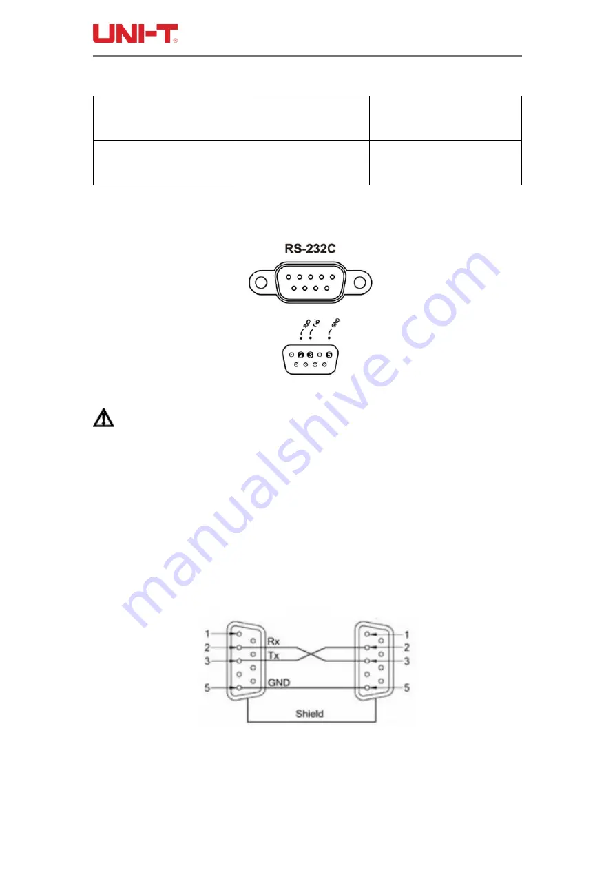
Figure 10-1-1 RS-232 Interface on the Rear Panel [Male]
Suggestion: To avoid electrical shock, please turn off the power of the instrument
when plugging or unplugging the connector.
The default communication settings of the instrument:
Transmission Mode: full-duplex asynchronous communication including start bit and stop
bit
Data Bit: 8 bits
Stop Bit: 1 bit
Check Digit: None
10.1.2 Connection Mode
Figure 10-1-2 RS-232 Interface on the Rear Panel [Male]
The RS-232 serial interface can be interconnected with the serial interface of the controller
(for example: personal computer or industrial computer) through a 2-3 crossed DB-9 cable.


