UT3550 Battery Tester Users Manual
13
Preparation before Measurement
3.1
Power on and Run
3.1.1
Power on and off
Turn on power switch
,
when indicator light display green
(
no power supply
),
it
presents the power has been turn on.
3.1.2
Introduction of Test Lead
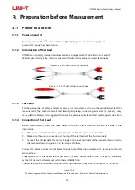
UT3550 series battery internal resistance tester is equipped with UT-L84 kalvin clips and UT-
L86 test pen-crown probe, which is convenient for users to measure more professionally.
Figure 3-1-2 a UT-L84 Kalvin Clips Test Wire
Figure 3-1-2 b UT-L86 Test Pen-Crown Probe
3.1.3
Test Lead
For the perspective of safety and test accuracy, it is recommended to use the standard test lead for
measurement. The contact suface of test lead is gold plating, in the long-term work (1~2 year), it may
cause plating abrasion, it is suggested that user to replace new test lead if test result appears deviation.
3.1.4
Connection of Test Lead
Before measurement, follow the steps below to connect the test lead to the test terminals of the
instrument
:
1.
Before connecting the test line, please make sure that the power switch is OFF;
2.
Make sure there is no connection at the top of the test leads of the four terminals;
3.
Connect the test leads of the four terminals to the input terminals of the instrument according to
the method shown in Figure 3-1-4, the steps as follows,
Connect the black test lead to the black terminal hole of the instrument and the red one to the red
terminal hole.
The
▲
symbol of the black test lead must match the black SENSE hole on the front panel, and the
▲
symbol of the red test lead must match the red SENSE hole.
The test lead must connect with terminal correctly, otherwise it may effect the output of test result.
Figure 3-1-4
Schematic Diagram of the Connection between the Test Lead and the Terminal Hole of the Instrument


