User’s Manual and UT5320R-SxA Series
34 / 43
Instruments.uni-trend.com
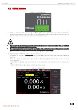
8.2 SIGNAL Interface
Figure 8-3 SIGNAL Interface
1)
SIGNAL interface provides
a power supply with an approximate output voltage of +24V (1 pin is +24V and 2
pin is ground),
output current is less than 0.5A and coordinate with HANDLER interface to control signal for
indicator light, optoelectronic switch and low power solenoid value.
This power is the the internal power of the instrument, AC current is output via rectifier filter, no stabilized
voltage about 24V, please confirm it befor using.
The maximum transient current cannot be greater than 0.5A, and the long-term working current cannot be
greater than 0.2A. If a larger current is required, please prepare a power supply.
2)
3 pin and 4 pin of SIGNAL interface is online lock signal,
<System Setup 2> page
,
if [Safety Lock] function is enabled, then online lock signal should provide by the
external.
Online lock signal only works when it is short circuit. Attached pluggable terminal is convenient for users
to connect wire.
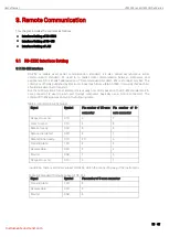
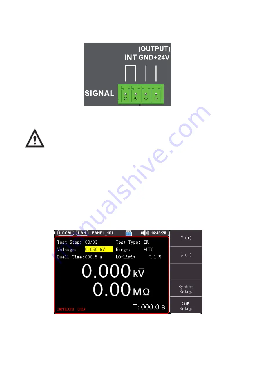
If the online lock signal is open circuit, then then instrument will be locked and cannot to start or stop the
test.
“INTERLOCK OPEN!” will also display on the measurement page.
Figure 8-4 Interlock Open
3


