User’s Manual and UT5320R-SxA Series
6 / 43
Instruments.uni-trend.com
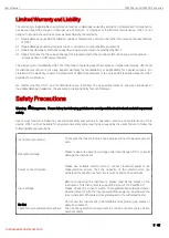
1.3 Prohibited Operation
Do not turn on/off the power repeatedly
After turning OFF the power switch, be sure to allow several seconds or more before turning it ON again. Do not
repeat turning ON/OFF the power switch rapidly. If you do this, the protective measures of the tester may not
be functioned properly. Do not turn OFF the power switch when the tester is delivering its test voltage–you may
do this only in case of emergency.
Do not short the output to the earth ground
Pay attention so that the high test voltage line is not shorted to a nearby AC line or nearby devices (such as
conveyors) which are connected to an earth ground. If it is shorted, the tester chassis can be charged up to the
hazardous high voltage.
Do not apply an external voltage
Do not connect any external voltage to the output port of the instrument. The instrument has no external
discharge function in non-discharge condition,
The analog voltmeter on the front panel cannot be used as stand-alone voltmeter. They may be damaged if their
output terminals are subject to an external voltage. The output port connect to the external voltage may cause
damage to the instrument.
1.4 To Ensure Long-Term Use without Failures
It is recommend to use the instrument in the range as follows.
Ambient
Temperature
Maximum Output Power
Pause Time
Limited Output
Time
T≤40
℃
AC
Withstand
Voltage
>12mA
(/S4A/S8A)
>6mA (UT5310A/D/R+)
At least as long as the
output time
Maximum
of
120 seconds
DC
Withstand
Voltage
>6mA
(/S4A/S8A)
>3mA (UT5310A/D/R+)
At least as long as the
output time
Maximum
of
120 seconds
Note: Output time = (voltage rise time + test time + voltage fall time)
1.5 Daily Inspection
To avoid accidents, confirm the several things at least the following before starting operation:
1. The input power source complies with the standard and the tester’s power configuration is correct.
2. The tester is connected to earth ground.
3. The coating of the high-voltage test lead wire is free from cracks, fissures, and breakage.
4. Without connecting the test lines, the instrument can finish the test successfully when starting test by default.
5. The tester generates FAIL signal when the test wire is start to testing, low-voltage end of test lead contact with
high-voltage end.


