21
¡
¡
¡
¡
¡
¡
¡
¡
¡
¡
¡
¡
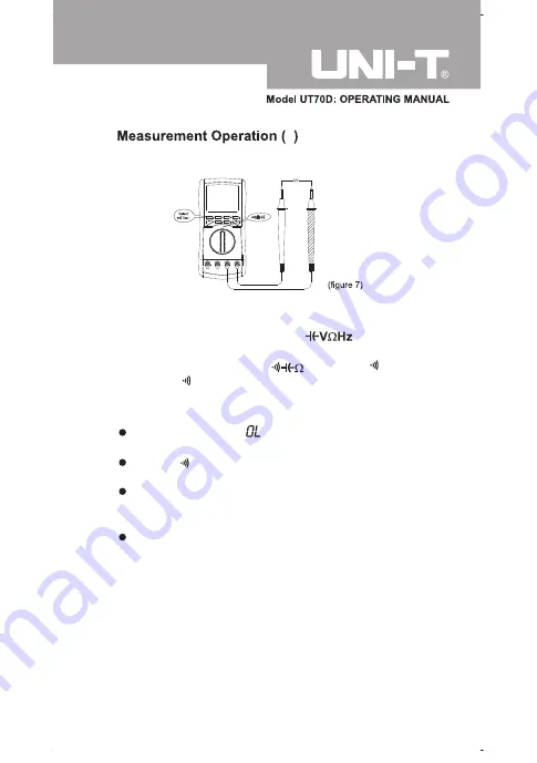
Continuity Measurement
(see figure 7)
6
To measure the continuity, connect the Meter as follows:
1. Insert the red test lead into the terminal and
the black test lead into the
COM
terminal.
2. Set the rotary switch to and press to
select measurement mode.
3. The buzzer sounds if the resistance of a circuit under
test is less than 100
¡
.
The
LCD
displays
indicating the circuit being
tested is open.
Press while turning on the Meter to disable the
beeper of pressing any button.
Although it is possible to select frequency and duty
cycle measurement mode, these functions cannot
be used.
When continuity testing has been completed,
disconnect the connection between the testing leads
and the circuit under test. and remove the testing
leads away from the input terminals of the Meter.
Summary of Contents for UT70D
Page 8: ...The Meter Structure see figure 1 ...
Page 12: ...Display Symbols 1 see figure 2 No Symbol Meaning 8 6 4 3 ...
Page 13: ......
Page 34: ...34 Turning on the Display Backlight ...
Page 35: ...35 ...
Page 41: ...41 5 Duty Cycle 1 99 600Vp ...
Page 43: ...43 MAINTENANCE 2 ...
Page 44: ...44 MAINTENANCE 3 ...
Page 46: ...46 B Setting of RS232C Serial Ports see figure 15 ...


