UTG1000A Series 11
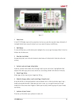
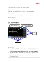
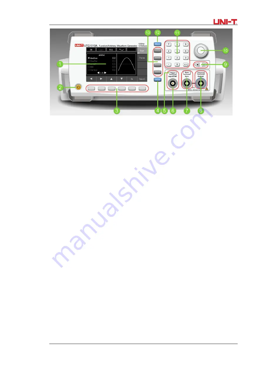
Figure 2-1
1.
Display Screen
4.3-inch TFT LCD displays high-resolution output state, function menu, and other important channel information. It
is designed to make human-computer interaction more convenient to improve work efficiency.
2.
On/Off Button
To turn on/off the device, press this button and its backlight will turn on (orange), the display will show the function
interface after the boot screen.
3.
Menu Operation Softkeys
Correspondingly select or check the label contents by identifications of softkey labels (at the bottom of function
interface).
4.
Auxiliary Function and System Settings Button
This button includes 3 function labels: Channel settings, frequency meter, and system. A highlighted label (the
midpoint of the label is gray and font is pure white) has a corresponding sub label at the bottom of the display.
5.
Manual Trigger Button
Setting trigger, and carrying out manual trigger when flashing.
6.
Modulation/Frequency Meter Input Terminal/Trigger Output Terminal
During AM, FM, PM or PWM signal modulation, when modulation source is external, modulation signal is input
through external modulation input. When frequency meter function is on, the signal to be measured is input
through this interface; when manual trigger for channel signal is enabled, manual trigger signal is output through
this interface.
7.
Synchronous Output Terminal
This button controls whether open synchronous output or not.
Summary of Contents for UTG1000 Series
Page 2: ......
Page 90: ...88 UTG1000A Series This user manual may be revised without prior notice...
Page 91: ...UTG1000A Series 89...


