38 UTG1000A Series
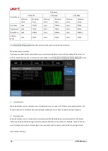
Arbitrary
Wave
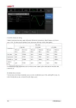
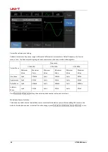
1μHz
3MHz
1μHz
2MHz
1μHz
1MHz
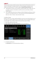
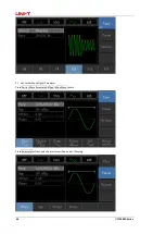
Press Parameter
→
Frequencysoftkey to enter carrier wave frequency setting, then enter required numerical value,
and select unit.
Modulation Source Selection
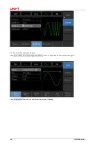
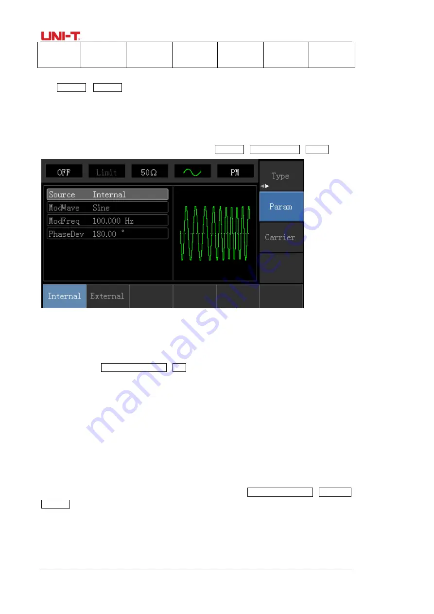
This device can select internal modulation source or external modulation source. After enabling PM function, the
default of modulation source is internal. If need to change, press Parameter
→
ModulationSource
→
External in turn.
1)
Internal Source
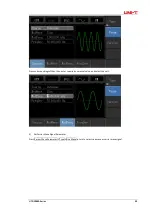
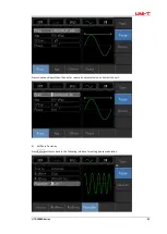
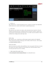
When modulation source is internal, modulation shape can be: sine wave, square wave, rising ramp wave, falling
ramp wave, arbitrary wave and noise. After enabling PM function, the default of modulation wave is sine wave. If
need to change, press Carrier Wave Parameter
→
Type in turn.
2)
External Source
When modulation source is external, carrier waveform will be modulated by an external waveform. PM phase
deviation is controlled by ±5V signal level of external modulation input terminal on front panel. For example, if
phase deviation value in parameter list has been set to 180º, +5V of external modulation signal is equivalent to 180º
phase shift.
Modulation Shape Frequency Setting
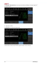
When modulation source is internal, frequency of modulation shape can be modulated. After enabling PM function,
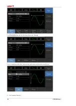
the default of modulation shape frequency is 100Hz. If need to change, press Carrier Wave Parameter
→
Modulation
Frequency in turn, and the modulation frequency range is 2mHz to 50kHz. When modulation source is external,
carrier waveform will be modulated by an external waveform. The range of modulation signal input from external is
0Hz to 20Hz.
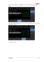
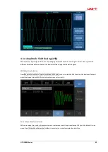
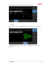
Phase Deviation Setting
Summary of Contents for UTG1000 Series
Page 2: ......
Page 90: ...88 UTG1000A Series This user manual may be revised without prior notice...
Page 91: ...UTG1000A Series 89...

