
5
f
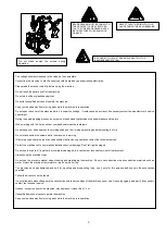
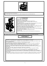
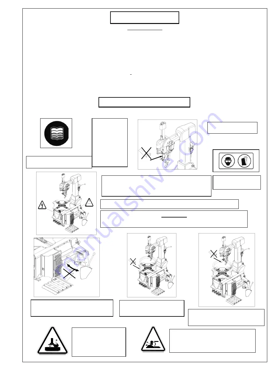
ATTENTION !
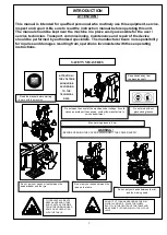
This manual is intended for qualified personnel who routinely use this equipment, service,
inspect and repair it. Be sure to read the instruction manual before operating this unit.
The manual should be kept near the machine in a place easily accessible for the user /
service technician. Transport, commissioning, maintenance and repair of the device
should be performed by authorized specialists. The manufacturer bears no responsibility
for injuries and damages resulting from operations inconsistent with these operating
instructions.
ATTENTION !
THE VOLTAGE
SHOULD BE
ACCORDING
TO THE
TECHNICAL
DATA
Read the manual before starting
to work with the machine
Do not work without
gloves and glasses
Keep hands away from
the machine shaft.
Do not open the cover of the machine under voltage. It could
cause an accident. If necessary, contact the manufacturer's
service department.
WARNING !
BEFORE OPENING THE COVERS DISCONNECT THE POWER SUPPLY.
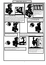
Do not get your hands or feet between the
bead-breaker and the tyre.
Do not put your hands between the
jaws on the table.
Do not put your hands between the rim
and the working head
Max. working pressure 8 bar.
INTRODUCTION
INTRODUCTION
IN
TRODUCTION
INTRODUCTION
SAFETY MEASURES
TO PREVENT ACCIDENTS
KEEP HANDS AND OTHER
BODY PARTS AS POSSIBLE
FROM THE WORKING HEAD
ARMS WHILE OPERATING
WITH THE TABLE.
DO NOT PUT YOUR HANDS UNDER THE RIM
WHILE CLAMPING IT. PLACE THE WHEEL
EXACTLY IN THE CENTER OF THE TABLE AND
MAKE SURE IT IS FIXED WELL WITH ALL FOUR
JAWS
DİKKAT
ÇALIŞMA BASINCI : MAX 8 BAR
ŞARTLANDIRICISIZ
ÇALIŞTIRMAYINIZ


