background image

16 


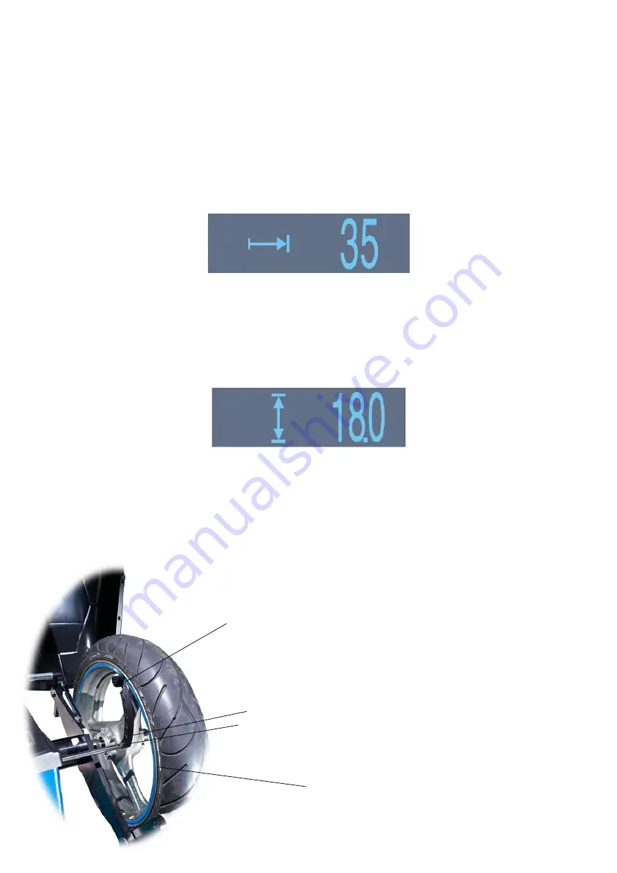
6.1.2 OFF-SET. 


Press D until the display show set-off symbol and its last entered value. Move adjust

er’s head 

(1) to rim (4) (Fig.10). 

Adjuster’s nonius show the set-off value (3). Insert this value pressing 

(+) or (-). 


6.1.3 DIAMETER. 


Press D until the display show diameter symbol and its last entered value.  Pressing (+) or (-) 
we change this parameter one inch from 10 till 30. 


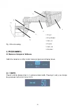
                    Fig.10 Parameters entering by adjuster. 

1. Adjuster head 

2. Adjuster arm 

3. Adjuster rod 

4. Rim  

2


Summary of Contents for TROLL MICRO M

Page 1: ...Operation and Maintenance Manual Wheel Balancer Model TROLL MICRO M Manufacturing Sales Maintenance UNI TROL Sp z o o ul Estrady 56 01 932 Warszawa tel fax 0 22 817 94 22 834 90 13 834 90 14 ...

Page 2: ...M Serial number Manufacturing year MANUFACTURER UNI TROL Sp z o o ul Estrady 56 01 932 Warszawa tel fax 0 22 817 94 22 834 90 13 834 90 14 AUTHORISED SERVICE CENTRE UNI TROL Sp z o o ul Estrady 56 01 932 Warszawa tel fax 0 22 817 94 22 834 90 13 834 90 14 wew 131 e mail serwis unitrol pl ...

Page 3: ...5 6 1 1 WIDTH 15 6 1 2 OFF SET 16 6 1 3 DIAMETER 16 6 1 4 Balancing programme selection 17 6 1 5 Accuracy 17 6 1 6 Balancer memory User memory 17 6 1 7 Balancer drive 18 6 2 Wheel balancing 18 6 2 1 Imbalance recalculation 23 6 2 2 Hidden weight programme 23 6 3 Calibration with calibrating device 24 6 3 1 Calilbration with wheel 26 7 MAINTENANCE 26 8 SCRAPPING 27 ...

Page 4: ...d in several ways Pallet stretch film cardboard box Pallet stretch film Pallet cardboard box Stretch film Transportation The packaging must be lifted or moved by means of forklift or pallet trucks Upon delivery of the load to the place of destination it is required to check if it has not been damaged during transportation It is also necessary to check completeness of the delivery against the waybi...

Page 5: ... Basic concepts general principles for design Part 1 Basic terminology methodology PN EN ISO 12100 2 2005 Safety of machinery Basic concepts general principles for design Part 2 Technical principles orig PN EN 61000 6 3 2002 Electromagnetic compatibility EMC Part 6 3 Generic standards Emission standard for residential commercial and light industrial orig PN EN 61000 6 4 2002 Electromagnetic compat...

Page 6: ... for any personal injuries or damages of vehicles or any other objects if any of the aforementioned operations have been performed in a manner non compliant with this manual or if the wheel balancer has been used improperly The manual includes only these maintenance and safety aspects which may help an operator or maintenance worker to understand better the construction and operation of the wheel ...

Page 7: ...idth 2 15 balancing accuracy 1g measuring time 6 7 s balancer s weight 60 kg dimensions with hood opened 880x800x1400mm with hood closed 880x550x1080mm max wheel weight 60 kg rotation speed 140 170 rpm driving motor power 80 W power supply 230V 50Hz noise level 65 dB ...

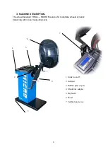
Page 8: ...The wheel balancer TROLL MICRO M serves for motorbike wheels dynamic balancing within one measuring cycle 1 Switch on off 2 Adjuster 3 Rubber pads 4 pcs 4 Motorbike adapter 5 Keyboard 6 Hood 7 Calibration device 7 6 5 1 2 4 3 ...

Page 9: ...tatic Wheel parameters off set diameter width Balancing accuracy Measuring cycle stop STOP Measuring cycle start START Imbalance recalculating Calibration Hidden weight programme Memory M1 M2 programme 1 adhesive weights programme 2 static balancing for thin rims by one weight Sound signal confirms button pressing ...

Page 10: ...used by improper or unauthorised use of the wheel balancer ATTENTION IT IS NOT RECOMMENDED TO USE THE WHEEL BALANCER WITHOUT PRIOR CLOSURE OF THE WHEEL GUARD FAILURE TO MEET THE AFOREMENTIONED REQUIREMENTS MAY RESULT IN SERIOUS PERSONAL INJURIES AND IRREPARABLE DAMAGE TO THE WHEEL BALANCER AND THE WHEEL General precautions The operator and maintenance worker are required to follow the safety regul...

Page 11: ...EPT CLEAN AT ALL TIMES Immediately remove any oil stains Risk of electric shock Danger of electric shock in the areas where electric wiring is routed It is forbidden to use water or vapour atomizers high pressure washing equipment solvents or paints near the machine These substances must not be allowed to spread to the control panel Dangers caused by inadequate lighting The operator and maintenanc...

Page 12: ... supply source and compressed air system The wheel balancer may be placed on any even stable and dry floor All the parts must be uniformly lit with the light sufficient to safely perform all the operational adjustment and maintenance operations mentioned in this manual Presence of any shaded areas light reflections and blinding light is inadmissible any situations which may cause eye strain should...

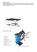
Page 13: ...with an oil wetted cloth Mount the adapter onto the shaft and tighten up the adapter to the shaft with the use of screw Fig 3 Motorbike adapter Fig 4 Wheel mounting on adapter 1 Adapter rod 2 Tyre tighter 3 Adapter axle 1 pc 4 Conus sleeve 2 pcs 5 Distance sleeve 6 pcs 6 Adapter nut 1 pc 7 Mounting screws 4 pcs 2 4 6 5 1 ...

Page 14: ...POUR CONDENSATE IT IS FORBIDDEN TO PLUG IN COOLED WHEEL BALANCER TO THE POWER NETWORK BEFORE THE LAPSE OF 2 TO 3 HOURS REQUIRED TO DRY THE ELECTRONIC ELEMENTS AND THEIR REACHING THE WORKSHOP TEMPERATURE FAILURE TO COMPLY WITH THIS REQUIREMENT MAY CAUSE DAMAGE TO THE WHEEL BALANCER AND WITH FAULTY ELECTRICAL INSTALLATION IT MAY CAUSE ELECTRIC SHOCK Hood Mounting Fig 5 Screw the hood holder 2 to mac...

Page 15: ...ch the balancer on After control test and signal sound display shows 6 1 1 WIDTH Press D until the display show and last entered width Pressing and we change this parameter half an inch from 2 till 15 1 Hood 2 Hood holder 3 M6 x 15 4 Socket 5 M8 x 80 6 Distance 6 5 4 2 3 1 ...

Page 16: ... 10 Adjuster s nonius show the set off value 3 Insert this value pressing or 6 1 3 DIAMETER Press D until the display show diameter symbol and its last entered value Pressing or we change this parameter one inch from 10 till 30 Fig 10 Parameters entering by adjuster 1 Adjuster head 2 Adjuster arm 3 Adjuster rod 4 Rim 1 2 4 3 ...

Page 17: ... balancer has three accuracy level 2 g 5 g 10 g Pressing or we increase or decrease accuracy When result is lower than accuracy level set display shows 0 ATTENTION If we press and hold STOP and then press Q we will switch the accuracy level off value Q 0 6 1 6 Balancer memory User memory Balancer has two memories M1 M2 which make possible to memorize the parameters for two wheels To insert data in...

Page 18: ...n it is enough to press button or to enter data on this wheel Upon entering the measuring setpoints the wheel should be brought up to speed of at least 95 rpm The measuring cycle is conducted with no interference on the side of the operator and is completed by displaying the value of imbalance in the indicator screen The indicator screen displayed exemplary values of imbalance 15 g applicable to i...

Page 19: ...gainst the topmost point of the rim defined by the machine Thus there may be a case when after a control measurement one gets a result of for example 6 g for the inner plane and 7 g for the outer one What to do next Case 1 The indicator displays value 0 It signifies that the wheel has been balanced with the accuracy up to 5 g since such a cut off threshold had been adopted By pressing button and s...

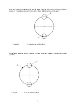
Page 20: ...20 If new position of imbalance is the same as the previous one or it differs to only a small extent the weight should be larger 1 weight 2 new correction position ...

Page 21: ...of the previously attached weight or it is slightly moved from this point the weight should be decreased 1 weight 2 new correction position If previously attached weight is below the new correction position it should be moved upwards 2 1 weight 2 new correction position ...

Page 22: ...te If the indicator screen displays 0 no imbalance there are no signals regarding the position of imbalance no arrows It may occur that in subsequent measurements of the wheel imbalance with the cut off threshold set to e g 5 g the results will change as follows first measurement 0 second measurement 6 g third measurement 0 etc The results are not incorrect The imbalance is certainly close to the ...

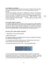
Page 23: ...nt 5 and 6 The programme enables to split the imbalance displayed in the indicator screen between two correction weights which should be stuck behind two arms of the rim spokes located in the nearest distance to the left and right from the imbalance position Procedure of the hidden weight programme 1 Select variant 2 from ALU programme 2 Start measuring cycle 3 If imbalance position is on spoke im...

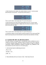
Page 24: ...ed exit the programme 3P by pressing STOP Start measuring cycle and check whether the wheel has been balanced correctly 6 3 CALIBRATION WITH CALIBRATING DEVICE The wheel balancer is equipped with a self calibration system enabling the user to calibrate the machine himself Calibration shall be performed in the case of suspicion of incorrect indications displayed by the machine caused by aging of el...

Page 25: ...balancer s drive on 4 Calibrating cycle finish when display shows figures 0 and 59 or 0 and 60 ATTENTION If display shows other figures that means wrong calibration contact service If there is no calibrating device calibration can be done by balanced wheel and weight of 60g 1 Calibration device screwed to tighter 2 Calibration device position 1 2 ...

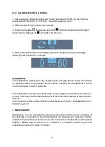
Page 26: ...riod without consulting the manufacturer s service centre shall result in loss of guarantee The manufacturer reserves the right to make design changes or add improvements to its product which may result in discrepancies with the information included in this operation manual If you have any doubts please contact us via telephone or email serwis unitrol pl 22 834 90 14 ext 131 7 MAINTENANCE Maintena...

Page 27: ... used as metal scrap In any cases of scrapping the machine neutralization of all the materials must be conducted in accordance with the regulations applicable in the country of the machine installation It should also be noted that for taxation purposes efficient hibernation of the machine must be documented in reports and forms compliant with the law applicable in the country of the machine instal...

Reviews: