20 UNIBLOC-PD Operation & Service Manual: PD200-576
4.4.2 Flushed Single Mechanical Seal
The flushed single mechanical seal uses the same stationary mating ring, rotating seal nose ring, spring, and o-rings as the single
mechanical seal discussed in section 4.4.1. The drive collar is different, however. The flushed single mechanical is not available
for
UNIBLOC
200-0, 200, 250, and 275. See section 3.3 for more information about flushing systems.
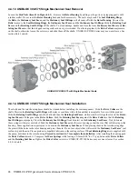
4.4.2.1 Flushed Single Mechanical Seal Removal
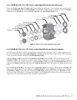
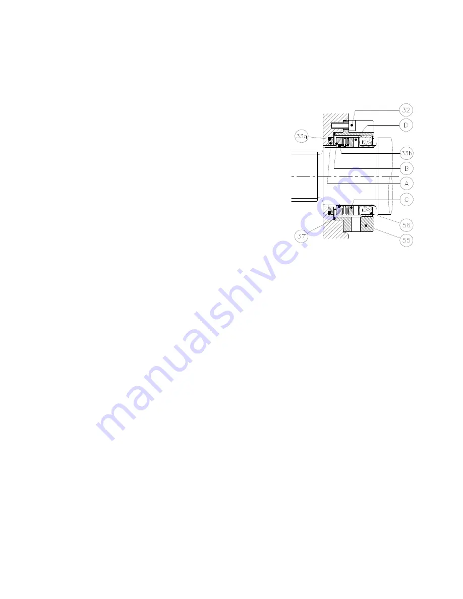
Disconnect the flush tubing from the flush housings (55). Loosen the set screws
(D) by inserting an allen wrench into the flush housing port holes. Loosen the
stud nuts (item 43 in Figure 4.4.1). Remove the rotor housing (1) by pulling on
the ports or by tapping gently with a rubber mallet and lay it rotor cavity down
so that the seals face up. Do not rock the housing back and forth excessively
or let it come in contact with the shaft splines. The seals may break. The entire
seals with the flush housings will come off intact with the rotor housing. Un
-
screw the bolts (32) to remove the flush housings (55), the lip seals (56), and
the flush housing o-rings (37). The remaining seal components may now be re
-
moved. To avoid damage, handle and store the loose seal nose rings (B) and the
mating rings (A) so that their lapped sealing surfaces do not get scratched. To
remove the lip seals (56), place the flush housings so that they are supported at
the bolt holes not at the at the o-ring (37) location. This can be done by placing
the flush housings, after all other seal parts have been removed, back into the
rotor housing seal bores. Push or tap the lip seals with a tube to remove them.
4.4.2.2 Flushed Single Mechanical Seal Installation
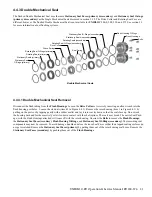
Place the mating ring o-rings (33a) in the rotor housing seal bores. Only lubricate these o-rings with water or alcohol. Push the
mating rings into the rotor housing so that they seat flat with the step in the housing. Do not use objects that will scratch the
mating rings’ seal surface to push them in. Check the drive collars (C) for wear at the lip seal location. If a groove is present, the
drive collars may need to be replaced. If the lip seals (56) have been removed, place the flush housings (55) so that the o-ring
groove edges face up. Lubricate the lips and the outer diameters of the lip seals. Push the lip seals, spring sides facing up, into
the flush housings with a tube that is the same diameter as the lip seals. Place the o-rings (37) into the o-ring grooves. Lubricate
the shafts, the outside of the plastic mounting sleeves, and the drive collars at the lip seal location. Slide the flush housings on the
drive collars. Slide the flush housings with the drive collars, seal nose o-rings (33b), and the seal nose rings (B), slotted sides first,
on the plastic mounting sleeves. Align the slots with the pins in the drive collars and push the seal nose rings so that the o-rings
(33b) seat properly. Place a product compatible lubricant on the sealing surfaces. Rotate the flush housings so that its port holes
align with at least one set screw. Lubricate the o-rings (37) and mount the seal cartridge assemblies on the rotor housing. Tighten
the bolts (32).
See section 4.4.7 to complete the installation.
Summary of Contents for 54001010P20H6010T12E
Page 42: ...42 UNIBLOC PD Operation Service Manual PD200 576 UNIBLOC PUMP ...
Page 43: ...UNIBLOC PD Operation Service Manual PD200 576 43 UNIBLOC PUMP ...
Page 44: ...44 UNIBLOC PD Operation Service Manual PD200 576 UNIBLOC PUMP ...
Page 45: ...UNIBLOC PD Operation Service Manual PD200 576 45 UNIBLOC PUMP ...
Page 46: ...46 UNIBLOC PD Operation Service Manual PD200 576 UNIBLOC PUMP ...
Page 47: ...UNIBLOC PD Operation Service Manual PD200 576 47 UNIBLOC PUMP ...
Page 48: ...48 UNIBLOC PD Operation Service Manual PD200 576 UNIBLOC PUMP ...
Page 49: ...UNIBLOC PD Operation Service Manual PD200 576 49 UNIBLOC PUMP ...
Page 50: ...50 UNIBLOC PD Operation Service Manual PD200 576 3 ...
Page 51: ......
Page 52: ......


