Unibor E50 FRV Manual
Original Instructions
Nov 2019
12
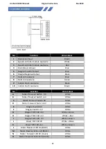
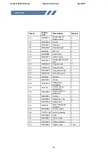
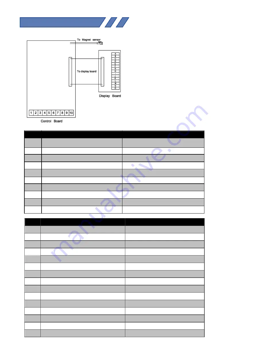
14) WIRING DIAGRAM
No
Function
Wire Colour
1
Mains Live Input
Brown
2
Speed controller module Lead wire
White
3
Speed controller module Lead wire
Red
4
Mains Neutral Input
Blue
5
Magnet Positive Output
Blue
6
Magnet Negative Output
Black
7
Field coil Lead wire
Blue
8
Field coil Lead wire
Green
9
Carbon brush Lead wire
Black
10
Carbon brush Lead wire
Brown
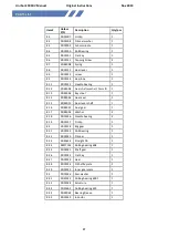
No
Function
Wire Colour
A
Motor 'Reverse' Switch 0V
White
B
Motor 'Reverse' 5V
White
C
Motor 'Forward' Switch 0V
White
D
Motor 'Forward' 5V
White
E
Magnet Switch 0V
White
F
Magnet 5V
White
G
Magnet 'ON' LED +5V
White + Green
H
Magnet 'ON' LED +5V
White + Red
I
Magnet 'ON' LED 0V
White + Brown
J
Power 'ON' LED 0V
White + Black
K
Power 'ON' LED +5V
White + Brown
L
Motor 'Reverse' LED OV (BLUE)
White
M
Motor 'Reverse' LED +12V (BLUE)
White
N
Motor 'Forward' LED 0V (Green)
White
O
Motor 'Forward' LED +12V (Green)
White


