Unibrain Fire-i 530/550/630/830/850 Operation Manual
Page 55
4.9.
Serial Interface
The cameras are equipped with the SIO (Serial input/output) feature described in the IIDC 1.31 specification. By
using the serial interface, the user can execute commands by writing data in a specific address in the FireWire
address range. SIO can be further used as an RS232 interface which supports pass through and custom commands.
4.9.1.
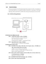
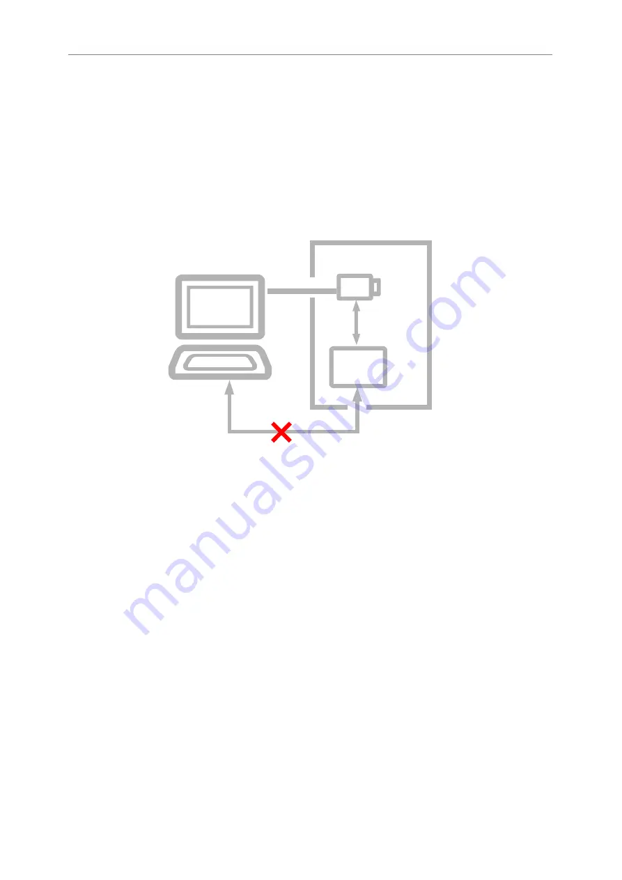
SIO Pass Through Scheme
User Target System
SIO(RS232) Pass Through
Camera
FIREWIRE�
Cable
RS232C
System�
Controller
SIO (RS232) Control Setting Procedure
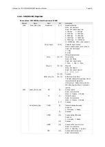
STEP 1. Configuration of Registers Address : F2F22000h
Baud Rate : 9600, No Parity, 1 bit Stop, 8 bit data length
Write : F2F22000h, Data = 050800000h
Value read after write = 050800020h 20 is the buffer of TX and RX
STEP 2. Enable RS232 TX / RX Address : F2F22004h
Write Data : C00000000 : Now RS232 TX / RX port is enabled
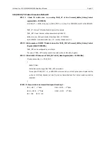
SIO (RS232) RX Control Procedure
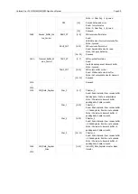
STEP 1 Read RBUF_ST of the Receive Buffer Status Control Register (address : F2F22008h) and
check number of RX data buffered in the camera.
If (RBUF_ST !=0) the RX is Ready else RX is NOT Ready
RBUF_ST : The number of current data buffered in the camera (Unit : byte)
RBUF_CNT : READ : Remaining RX buffer size
STEP 2 Write number of RX data intended to read from RBUF_CNT of the Receive Buffer Status
Control Register (address : F2F22008h)
RBUF_CNT can be configured by unit of byte.
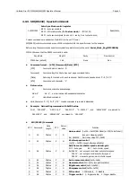
STEP 3 Read RS232 RX data from SIO_Data_Register (addr. : F2F22100 )
STEP 4 If data is further required repeat from STEP1


