6
User’s operating instructions
6.4 - FROST PROTECTION MODE
The boiler is fitted with a frost protection system which will
operate automatically when the system temperature falls be-
low 6°C: the burner is automatically fired and the pump is
energized until the system’s water temperature has risen to
16°C.
If the temperature detected by the CH sensor falls below 2°C,
burner operation is automatically stopped until the tempera-
ture has risen to 5°C.
D.H.W. production (Summer mode)
Make sure the selector (B) is in position (
)
Position the D.H.W. temperature adjusting
knob (C) on the desired temperature:
COMFORT
between 38 and 60°C,
ECO-
COMFORT
or
ECO
.
Note:
By adjusting the DHW temperature at a tem-
perature very close to the one actually used
will avoid mixing hot water with cold water,
thus resulting in fuel savings and a signifi-
cant reduction of lime scale formation.
When opening a D.H.W. tap the boiler will start automatically
in order to supply water at the desired temperature.
During all the phase of D.H.W. drawing,
on the display the actual D.H.W.
temperature and the symbol (
) are
shown.
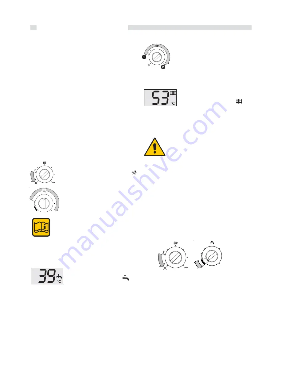
C.H. mode (Winter mode)
In order to have the boiler operating for C.H.
purposes, the pointer of the knob (B) has to
be positioned between 1 (minimum
temperature) and 2 (maximum
temperature).
If the C.H. installation is equipped with a Room thermostat,
position the pointer of the knob (B) in an intermediate position.
During the operation in C.H. mode, on
the display the actual boiler water
temperature and the symbol (
) are
shown.
Put out of operation
In order to put completely out of operation the boiler cut the
power supply to the boiler through the external main switch.
In case of long periods of inactive state of the
boiler close also the gas and cold water cocks.
B
C
To activate the anti-frost protection position the pointer of
knobs (B) and (C) as shown below.
MAX
MAX
6.2 - CHECK LIST BEFORE COMMISSIONING
THE BOILER
Before commissioning the appliance it is recommended to
check the following points:
-
Check that the On-Off gas valve, positioned upstream of
the boiler, is in the On position.
-
Check that any On-Off valves fitted on the flow and return
pipes for servicing purposes are in the On position.
-
Check that any On-Off valves fitted on the cold water inlet
for servicing purposes are in the On position.
-
Check that the pressure relief valve drainage pipe is con-
nected to the sewage system.
-
Check that the boiler is connected to the electrical supply;
the display on the panel board has to be illuminated.
-
Check the heating system pressure, indicated by the pres-
sure gauge. For correct operation the pressure should be
between 0,8 and 1 bar (with the pump not running).
If the pressure falls below 0,7 bar restore the correct pres-
sure by regulating the filling valve when the system is cold
and the boiler not operating (refer to paragraph 6.5).
6.3 - BOILER OPERATION


