17
Instructions for the installer
•
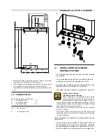
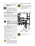
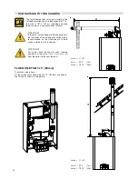
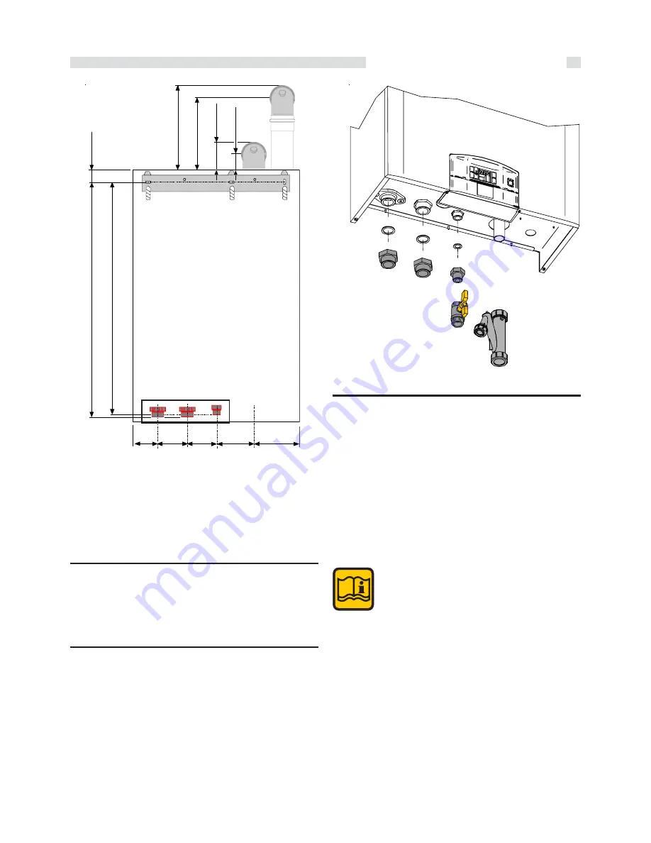
Mark the 3 holes with the wall bracket, using a spirit level.
•
Install the wall bracket with the 3 screws
•
With 2 people, lift the boiler by holding it by its back and by
the transport rail and install it on the wall bracket
•
The boiler can be moved sideways to get the correct posi-
tion.
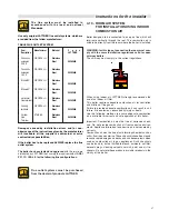
3.6 - CONNECTIONS
A)
Thread Adapter Kit NPT/gas
M
=
CH system flow
1’’¼
R
=
CH system return
1’’¼
G
= Gas Ball Valve
¾”
RG = Gas Adaptor ¾‘‘
S
= Condensate Drain
S
G
R
M
RG
3.7 -
INSTALLATION ON EXISTING
HEATING SYSTEMS
- The circulation pump’s output, the head and flow direction
are suitable.
- The gas feeding supply pipe and the eventual tank are
constructed according to the regulations in force.
- The expansion vessels assure the total absorption of the
dilatation of the fluid contained in the system.
- The system has been cleaned of impurities and lime scale.
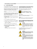
Boiler system flushing
(Not Boiler heat exchanger)
When replacing an existing boiler the heating
system should be flushed with the old boiler in
place before the new boiler is added to the sy-
stem. If the old boiler has already been removed a bypass
must be piped in when the new boiler is installed in order
to facilitate the flushing of the system.
The boiler must be valved off from the system, while the
system is flushed.
No system cleaner should ever enter the boiler heat
exchanger because of its caustic nature it could damage
the heat exchanger.
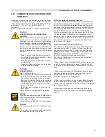
When the appliance is installed on existing systems, ensure
yourself that:
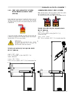
- The flue outlet pipe is suitable for condensing boilers, for
the temperature of the products of combustion, calculated
and manufactured according to the regulations in force. It
must be installed as much as possible in a straight line,
R
M
G
S
3.3’’
(85 mm)
4.3’’
(110 mm)
4.3’’
(110 mm)
5.2’’
(132 mm)
7.0’’
(177 mm)
33
.7
’’
(8
5
6
m
m
)
34.
1’
’
(8
65.
5 m
m
)
1.
8’
’
(4
.5
m
m
)
12.
3
’’
(3
1
1
,5
m
m
)
10
.4
’’
(265
m
m
)
4.
1
’’
(1
0
3
mm)
2.
2
’’
(5
6
.5
mm
)
0,5’’
(12 mm)
0,5’’
(12 mm)
0,5’’
(12 mm)
A


