22
Instructions for the installer
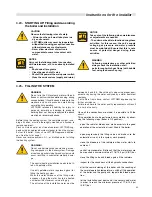
3.12 - WORKING PRESSURE
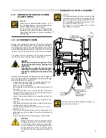
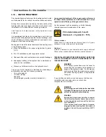
The boiler’s maximum allowable working pressure is set at
92 psa (634 kPa); whilst the minimum pressure is pre-
charged to 7,3 psa (50 kPa).
3.11 -
PRESSURE RELIEF VALVE DRAIN
PIPE
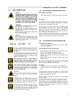
WARNING!
Please remember that it is forbidden to
interpose, between the boiler and the
pressure relief valve, any type of cutting-off
device. Moreover it is recommended to use
cutting-off valves which do not exceed the
maximum allowable operating pressure.
WARNING!
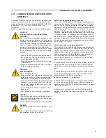
In correspondence to the heating pressure
relief valve foresee the installation of a
discharge pipe with a funnel and a siphon
which lead to an adequate drainage. The
drainage has to be controllable by sight.
If this precaution is not made, an eventual
intervention of the pressure relief valve could
cause injury to persons, animals or damage
to property. The manufacturer shall not be
held liable for any injury and/or damage.
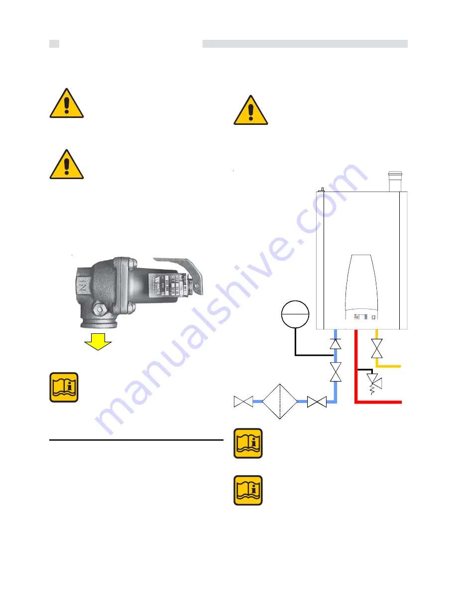
3.13 - CONNECTING THE EXPANSION
VESSEL IN A SINGLE BOILER
SYSTEM
CAUTION
Damage to the installation due to faulty
pressure relief valve.
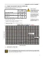
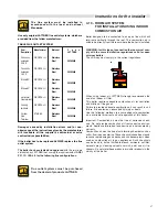
An expansion tank must be part of the central heating system.
The expansion tank must be appropriate to the water content
of the installation. The pre-charge pressure depends on the
installation height above the mounted expansion tank.
1
R
M
G
NOTICE
The expansion tank is NOT a part of the delivery
and should be sourced locally. Please refer to
the expansion tank manufacturer for further in-
formation.
Fill expansion tank to a minimum of 14.5 psi.
NOTICE
For the boiler to function correctly, it is necessary
to connect the expansion tank to the expansion
tank connection on the boiler. If the expansion
tank is not connected to the supplied connection
damage to the boiler may occur.
This reliev valve comply with the standard for
Relief Valves and Automatic Gas Shutoff
Devices for Hot Water Supply Systems ANSI
Z21.22b-01(R08)/CSA 4.4b-01(R08)
and/or the standard Temperature, Pressure,
Temperature and Pressure Relief Valves and
Vacuum Relief Valves CAN1-4.4-M80


