29
Instructions for the installer
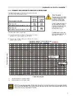
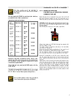
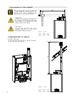
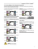
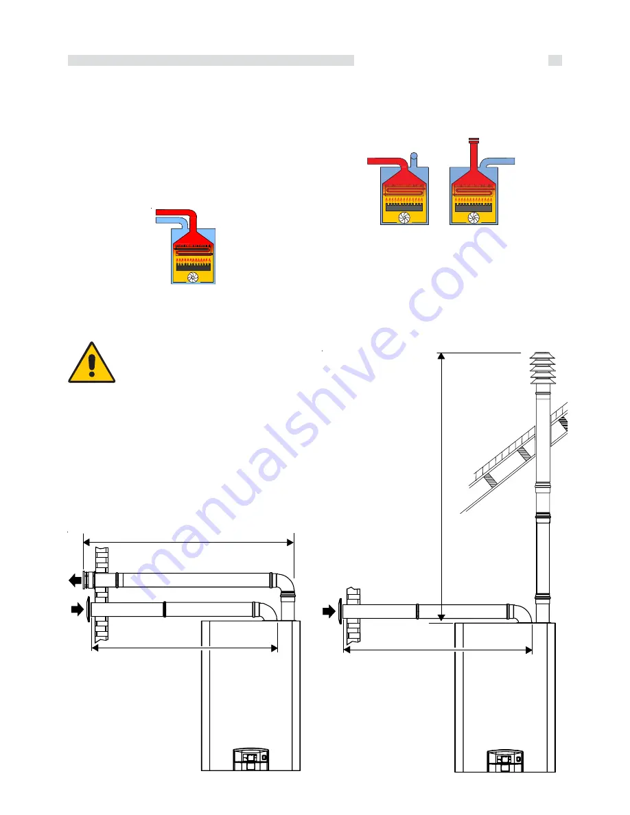
Smoke evacuation by two separate ducts
Ø 3.15‘‘ (80 mm)
L min = 78.7‘‘
(2m)
39.37‘‘ (1 m) air not less than 39.4 (1 m)
smoke evacuation
L max = 787.4‘‘ (20 m)
393.7‘‘ (10 m) air 393.7‘‘ (10 m) smoke evacuation
L
1
L2
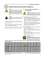
COMBINATION DIRECT VENT SYSTEM
Boiler with separate air inlet and products outlet. These ducts
can discharge into areas with different pressure.
The two terminals must not be fitted on to two opposite walls.
Boiler designed for connection to horizontal inlet and out- let
terminals, which admit fresh air to the burner and discharge
the products of combustion to the outside through concentric
or twin ducts.
The minimum distance between the inlet air duct and the flue
outlet duct must be of 9.8 in and both terminals must be posi-
tioned within a 19.6 in square section.
3.20 - VENT AND AIR SUPPLY SYSTEM
FOR ORIZONTAL DIRECT VENT
SYSTEM
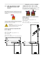
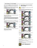
Smoke evacuation by two separate ducts
Ø 3.15‘‘ (80 mm)
L min = 78.7‘‘
(2m)
39.37‘‘ (1 m) air not less than 39.37 (1 m)
smoke evacuation
L max = 787.4‘‘ (20 m)
393.70‘‘ (10 m) air 393.7‘‘ (10 m) smoke evacuation
L1
L2
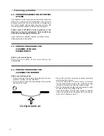
ATTENTION!
For boiler have horizontal runs sloping
upwards not less than 1/4 in / ft (21 mm / m)
from the boiler to the vent terminal.


