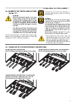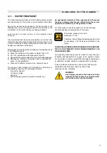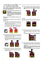
13
Instruction for the installer
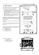
3.4 - BOILER LOCATION
When selecting the position for the installation of the boiler
please comply to the following safety requirements:
•
Fit the appliance in rooms protected from frost;
•
In rooms where aggressive vapours or dust are present,
the appliance must be able to operate independently from
the air of the location room;
•
The appliance must be installed exclusively on a vertical
and solid wall, capable of adequately supporting the
weight of the boiler;
•
The wall must not be made of inflammable material;
•
Leave on each side of the appliance a sufficient clearance
in order to allow easy service works.
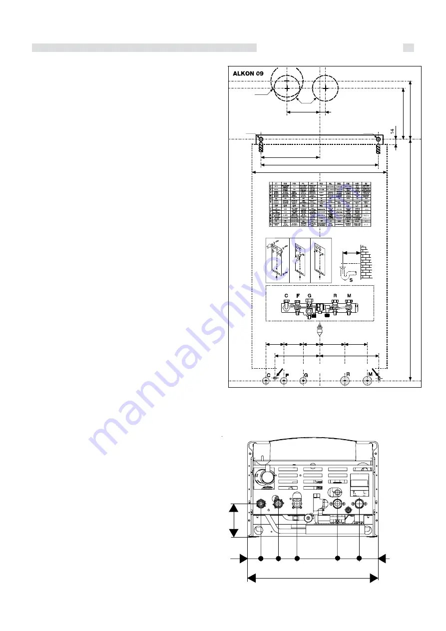
Every appliance is supplied with a paper “Wall mounting
template” which facilitates the connection of the gas and water
feed pipes when laying out the hydraulic system and before
installing the boiler.
This template has to be fixed on to the wall chosen for the
installation.
The upper part gives the indications to drill on the wall the
fixing holes for the boiler supporting bracket and for the rear
smoke outlet.
The lower part of the template marks the correct positioning
of the system pipework connections for the following parts:
M
=
CH system flow
(3/4“)
C
=
Hot water outlet
(1/2“)
G
=
Gas supply
(3/4“)
F
=
Cold water supply
(1/2“)
R
=
CH system return
(3/4“)
LOWER VUE OF CONNECTIONS
•
Filling valve (
Rc
)
•
Safety valve discharge (
Vs
)
•
Condensate evacuation (
Sc
)
•
C.H. system drain (
Si
)
10
7
43 56 60
130
70 61
420
C
F
G
Rc
R
M
Vs
Sc
Si
VIEW FROM BELOW
101
18
2
Ø12
420
366
183
752
56
60
51
79
70
139
185
Ø100
Ø80
19
Ø12
POUR VERSION FRANCE
160
POSITION DES FIXATIONS DE LA PLAQUE DE RACCORDEMENT
(POUR VERSION FRANCE)
143
Summary of Contents for ALKON R 18
Page 1: ...ALKON 09 R 18 C 18 R 24 C 24 00333176 2nd edition 10 2011 INSTALLATION AND SERVICING MANUAL...
Page 46: ......
Page 47: ......


