16
Instruction for the installer
Prevalenza Disponibile all'Impianto
0
0,2
0,4
0,6
0,8
1
1,2
1,4
1,6
1,8
2
2,2
2,4
2,6
2,8
3
3,2
3,4
3,6
3,8
4
4,2
4,4
4,6
4,8
5
5,2
5,4
5,6
5,8
6
0
100
200
300
400
500
600
700
800
900
1000
1100
1200
1300
1400
1500
portata (l/h)
p
reval
en
z
a
(
m
H2O
)
V1
V2
V3
3.7 - CENTRAL HEATING CONNECTIONS
WARNING!
Before installing the boiler we recommend
that the system is flushed out with a suitable
product in order to eliminate any metallic
tooling or welding residues, oil and grime
which could reach the boiler and affect the
proper running of the boiler.
Do not use any solvents for flushing out the
system as they could damage the system
and/or its components.
Non-observance of these instructions could
cause injury to persons, animals or damage
to property. The manufacturer shall not be
held liable for any such injury and/or damage.
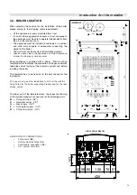
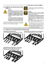
The CH flow and return circuits have to be connected to the
boiler via the respective connections ¾” M and R as indicated
on page 13.
When determining the size of the CH circuit pipes it is essential
to bear in mind the pressure losses induced by the radiators,
any eventual thermostatic radiator valves, lockshield valves
and by the system’s layout.
The routing of the piping has to be laid down taking all the
necessary precautions in order to avoid air locks and to
facilitate the continuous purging of the system.
Ensure yourself that the system’s piping is
not used as earth clamps for the electrical
or telephonic system. They are absolutely
unsuitable for this use. In a short time this
could cause serious damage to the piping,
boiler and radiators.
The boiler is fitted with an automatic BY-PASS (differential
valve with a flow rate of about 150 l/h) which always ensures
a minimum water flow rate to the heat exchanger even if, for
example, all the thermostatic valves fitted on the heating
system are closed.
Pressure relief valve drain pipe
In correspondence to the heating pressure relief valve
provision should be made to install a discharge pipe with a
funnel and a siphon which lead to an adequate drainage.
The
drainage has to be controllable by sight.
WARNING!
If this precaution is not taken it could lead to
injury to persons, animals or damage to
property.
The manufacturer shall not be held liable for
any such injury and/or damage.
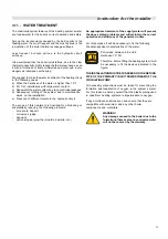
BOILER CIRCULATION PUMP
Graph – Water flow rate/ available head for installation– ALKON 24 kW
Manometric head available for C.H. system
Available head
(mc.a.)
Flow rate
(Q) l/h
Summary of Contents for ALKON R 18
Page 1: ...ALKON 09 R 18 C 18 R 24 C 24 00333176 2nd edition 10 2011 INSTALLATION AND SERVICING MANUAL...
Page 46: ......
Page 47: ......

