40
Instruction for the installer
C) COMPLETION OF THE BASIC
ADJUSTMENTS
- Check the C0
2
values at the minimum and maximum output.
- If necessary make the required adjustments.
To ensure correct boiler operation the C0
2
values have to be adjusted with extreme care
respecting the values indicated in the table.
-
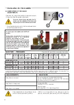
Close the sampling test point in the flue inlet/outlet termi-
nal with the appropriate cap C.
In case of gas valve replacement or difficult
ignition:
Screw down completely the maximum
adjustment screw “A“ in a clockwise
direction, than slacken for 7 turns.
Check the boiler ignition; if the boiler goes
into lockout slacken the screw “A“ again of
one turn, than retry ignition. If the boiler goes
into lockout again, carry out the above
indicated operations until the boiler is fired.
At this point carry out the burner adjustment
as previously indicated.
ALKON 09 R 24 - C 24
9,5
11,0
6800
6800
20
37
0,47 m³/h
0,34 kg/h
2,52 m³/h
1,85 kg/h
Nat. gas (G20)
LPG (G31)
1800
1800
-
8,8 x 8
9,5
11,0
5,6
5,6
-
-
50
50
ALKON 09 R 18 - C 18
9,5
11,0
5300
5300
20
37
0,47 m³/h
0,34 kg/h
1,90 m³/h
1,40 kg/h
Nat. gas (G20)
LPG (G31)
1800
1800
-
8,8 x 8
9,5
11,0
5,6
5,6
-
-
70
70
INCONVENIENTS
SOLUTIONS
Noisy flame at cold start
Act on the parameter IG via the REGOLAFACILE,
section “TECHNICAL MENU”, parameters TSP, increasing
the value by about 5-10% maximum.
Noisy flame in steady state
Increase the CO2
value by 0.2 to 0.4% maximum.
Noisy flame in modulation
These adjustments can be performed only by
Service Centres authorized by UNICAL.
In some geographical zones particular gas distributing conditions can occur, such as a different mixing of components: This
will require an optimization of the boiler calibration, which can be different than the one factory made.
UNICAL is not responsible for any damages caused to
persons, animals and goods deriving from this infringement
Check the C0
2
levels often, especially at low output
INJECTORS – PRESSURES
Fan
s p e e d
(rpm)
Gas type
Supply
p r e s s u r e
(mba r)
Min gas
consum-
ption
Collector
Diaphragm
(Ø and n.
holes )
Mixer
injector
(Ø mm)
Flue outlet
diaphragm
(Ø mm)
CO2
levels (%)
m i n
max
m i n
max
Start-up
firing rate
%
Max gas
consum-
ption
Min CO2 >= 9%
LPG: Max CO2 = 11% Min CO2 >= 10.2%
Summary of Contents for ALKON R 18
Page 1: ...ALKON 09 R 18 C 18 R 24 C 24 00333176 2nd edition 10 2011 INSTALLATION AND SERVICING MANUAL...
Page 46: ......
Page 47: ......

