15
2.7 - BURNER
2.7.2 - CHOICE OF THE BURNER
The correct choise and the adjustment of the
burner are foundamental for the best operation of
the boilerand then they shall be accurate and
not underevaluated.
The burner will be selected by verifying that
its working diagram (fuel flow rate - pressure in
the furnace) is compatible with the same
features declared for the boiler.
Remember that the smoke side resistance, i.e.
the counterpressure in the furnace, are referred
to "0" draught at the chimney base.
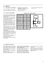
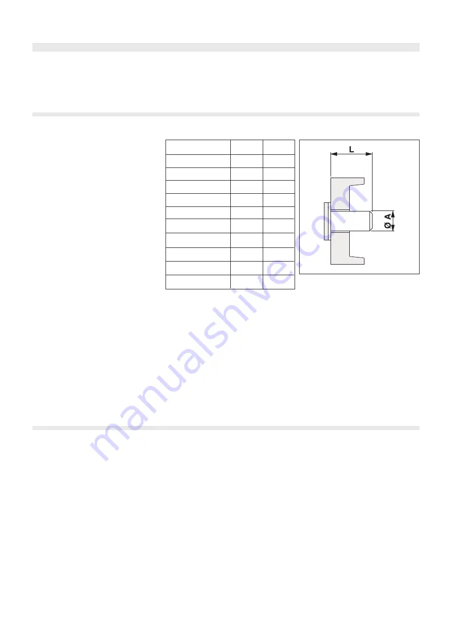
It is also convenient that the burner blast tube
have its length not shorter than that shown in
table 18 and that the flame have a shape
suitable to the characteristics of the ELLPREX
furnace.
In fact to better exploit all the heating surface of
the reversed flame furnace it is necessary to
use burners capable to guarantee a long and
narrow flame at all operating conditions or also
at minimum input in case of two stage or
modulating burners.
Too short flames can cause a localized
overheating of the front part of the furnace, and
the combustion products, not sufficiently cooled
down, entering the smoke pipes at a too
high temperature, can cause important da-
mages to the boiler.
The burner manufacturing companies are
able to supply the flame dimensions
developped by their burners.
More informations are given in the paragraph
"Commissioning".
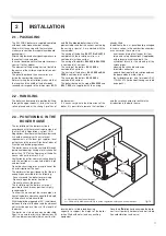
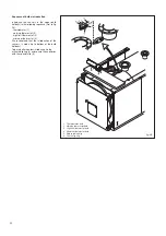
BOILER MODEL
øA
mm
L
mm
fig. 20
ELLPREX 2200 - 2650
380
350
ELLPREX 1570 - 1850
320
320
ELLPREX 1100 - 1320
320
300
ELLPREX 760 - 970
270
270
ELLPREX 290 - 630
220
250
ELLPREX 170 - 240
180
250
2.7.1 - CONFORMITY OF THE BURNER
All the burners equipping the ELLPREX boilers
must be CE certificated and must conform to
the following directives and standards:
- Gas Appliances Directive (90/396/CEE);
- EMC Directive (89/336/CEE).
- EN 267 - Automizing oil burners of
monobloc type - Testing -
- EN 676 - Automatic forced draught burners
for gaseous fuels.
ELLPREX 3000
380
400
BURNER BLAST TUBE MIN. LENGTH
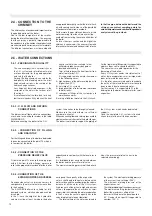
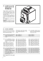
2.7.3 - BURNER INSTALLATION
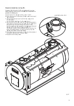
Before fitting the burner it is necessary to verify
the position of the turbulators inside the smoke
pipes: each pipe must have its turbulator and
this one has to be positioned as indicated in
the table on page 33.
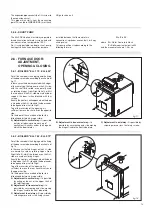
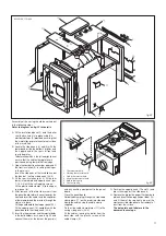
When mounting the burner to the boiler front
door, check for soundness around the burner
flange and its gasket.
Each boiler is supplied with a length of ceramic
fibre rope (cross section 25x25 mm).
This rope has to be put around the burner
tube to completely seal the tube and the
hole in the door insulation.
Be careful not to leave fissures between the
burner tube and the hole in the door.
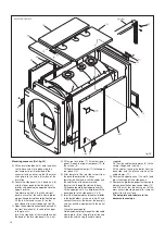
In case a cone, having a diameter langer than
the burner tube, the cone is to be removed
before fitting the burner and refitted later on.
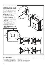
After the burner has been fitted, check that the
flexible hoses for the oil and the electrical cables
are long enough to allow the 90° opening of
the boiler door.
For gas burners the use of flexible pipes for
the gas is not allowed; so the final part of the
gas feeding line to the burner must have the
possibility to be removed, via a threaded or
flanged connection.
ELLPREX 3500 - 4000
400
400
ELLPREX 4500 - 6000
500
480
ELLPREX 6500 - 7000
500
630
Summary of Contents for ELLPREX Series
Page 1: ...26739 01 13 rev 4 ELLPREX INSTALLATION USE AND SERVICING INSTRUCTION to be kept by the user...
Page 37: ...37 Notes...
Page 38: ...38 Notes...
Page 39: ...39 Notes...


