16
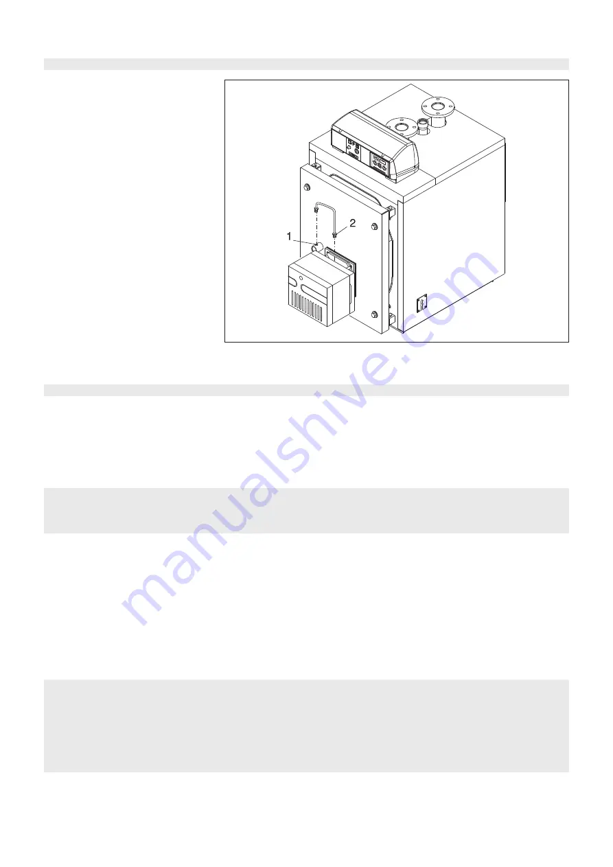
2.8 - CONNECTION OF THE
SIGHTGLASS TO THE
BURNER VIA A
COOLING LINE
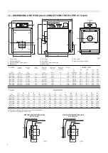
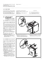
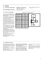
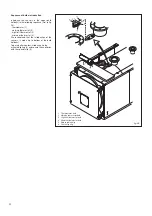
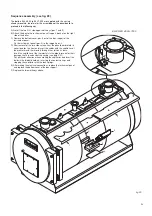
The flame sightglass is equipped with a 1/8"
threaded connection (pos. 1) on which
a pressure test nipple (9mm dia.) is fitted.
This can be used with a silicon pipe for the
measurement of the counterpressure in the
combustion chamber.
At the place of this pressure test nipple, which
must be held, a special microbore pipe (pos.
2) will connect the flame sightglass directly to
the pressure room downstream the fan of the
burner.
The air, blown by the fan, will cool down and
clean the sightglass.
If the sightglass is not cooled down it can be
brocken down.
WARNING: In the proximity of the sightglass
the temperature is very high: be careful!!!
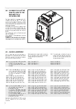
fig. 21
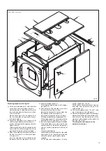
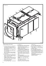
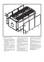
2.9 - CASING ASSEMBLY
N.B. It is suggested to verify that the boiler is
positioned in its final place and that all the
hydraulic connections are made correctly be-
fore starting the casing assembly.
29881 (ELLPREX 170)
29882 (ELLPREX 240)
29883 (ELLPREX 290)
30266 (casing front part ELLPREX 870)
29966 (casing rear part ELLPREX 870)
29963 (casing upper part ELLPREX 870)
30266 (casing front part ELLPREX 970)
29967 (casing rear part ELLPREX 970)
29964 (casing upper part ELLPREX 970)
30006 (casing front part ELLPREX 1100)
30007 (casing rear part ELLPREX 1100)
30008 (casing upper part ELLPREX 1100)
30006 (casing front part ELLPREX 1320)
30009 (casing rear part ELLPREX 1320)
29884 (ELLPREX 340)
29885 (ELLPREX 420)
29886 (ELLPREX 510)
30010 (casing upper part ELLPREX 1320)
29996 (casing front part ELLPREX 1570)
29997 (casing rear part ELLPREX 1570)
29998 (casing upper part ELLPREX 1570)
29996 (casing front part ELLPREX 1850)
30000 (casing rear part ELLPREX 1850)
30001 (casing upper part ELLPREX 1850)
30002 (casing front part ELLPREX 2200)
30003 (casing rear part ELLPREX 2200)
30004 (casing upper part ELLPREX 2200)
30002 (casing front part ELLPREX 2650)
30081 (casing rear part ELLPREX 2650)
30082 (casing upper part ELLPREX 2650)
30083 (casing central part ELLPREX 2650)
30111 (casing front part ELLPREX 3000)
30112 (casing rear part ELLPREX 3000)
30113 (casing central part ELLPREX 3000)
N.B.
For the model
ELL 2650
(ref. fig. 26)
the casing and the insulation are
contained in 4 cartons.
For the models
ELL 3000
&
ELL 3500
(ref. fig. 27), the casing and insulation
are contained in 3 cartons.
For the model
ELL 4000
(ref. fig. 27)
the casing and the insulation are
contained in 4 cartons.
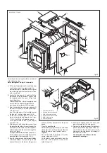
N.B.
For the models
ELL 170
to
ELL 510
(ref. fig. 22), the casing and the
insulation are contained in one carton
stamped:
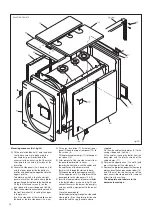
N.B.
For the model
ELL 630
(ref. fig. 22) and
for the models
ELL 760
to
ELL 2200
(ref. fig. 24 & 25), the casing and the
insulation are contained in 3 cartons
stamped:
29959 (casing front part ELLPREX 630)
29960 (casing rear part ELLPREX 630)
29961 (casing upper part ELLPREX 630)
30266 (casing front part ELLPREX 760)
29965 (casing rear part ELLPREX 760)
29962 (casing upper part ELLPREX 760)
Before opening the casing carton(s) make sure
they are stamped with the right boiler model,
corresponding to the boiler to be
installed.
N.B.: The packaging containing the panel
board is delivered inside the combustion
chamber, as well as the documents and
the guarantee certificate.
30114 (casing front part ELLPREX 3500)
30115 (casing rear part ELLPREX 3500)
30116 (casing central part ELLPREX 3500)
30114 (casing front part ELLPREX 4000)
30115 (casing rear part ELLPREX 4000)
30116 (casing central part ELLPREX 4000)
30543 (casing rear part ELLPREX 4000)
The boilers ELL 4500 to ELL 7000 (ref. fig.
29), are supplied with the casing already
mounted.
Summary of Contents for ELLPREX Series
Page 1: ...26739 01 13 rev 4 ELLPREX INSTALLATION USE AND SERVICING INSTRUCTION to be kept by the user...
Page 37: ...37 Notes...
Page 38: ...38 Notes...
Page 39: ...39 Notes...

